Liquid crystal display device and liquid crystal television

a technology of liquid crystal display device and liquid crystal television, which is applied in the direction of instruments, static indicating devices, etc., can solve the problems of user as a viewing audience to feel uncomfortable, the brightness of the screen to gradually decrease, etc., and achieve the effect of simple configuration

Inactive Publication Date: 2009-01-29
FUNAI ELECTRIC CO LTD
View PDF18 Cites 12 Cited by
  • Summary
  • Abstract
  • Description
  • Claims
  • Application Information

AI Technical Summary

Benefits of technology

[0024]Further, according to another aspect of the invention, the time-luminance correspondence recording unit can be recorded as data, the advantage of the invention can be obtained with a simple configuration.

Problems solved by technology

Therefore, the luminance on the screen decreases gradually to be darker, which causes the user as a viewing audience to feel uncomfortable.

Method used


Image

  • Liquid crystal display device and liquid crystal television
  • Liquid crystal display device and liquid crystal television
  • Liquid crystal display device and liquid crystal television

Examples


first embodiment

[0037]1. First Embodiment[0038]1-1. Configuration of Liquid Crystal Television[0039]1-2. Luminance Correction Method in Drive Beginning Period

[0040]2. Summary of First Embodiment

second embodiment

[0041]3. Second Embodiment

[0042]4. Summary of Second Embodiment

[0043]1. First Embodiment

[0044]1-1. Configuration of Liquid Crystal Television

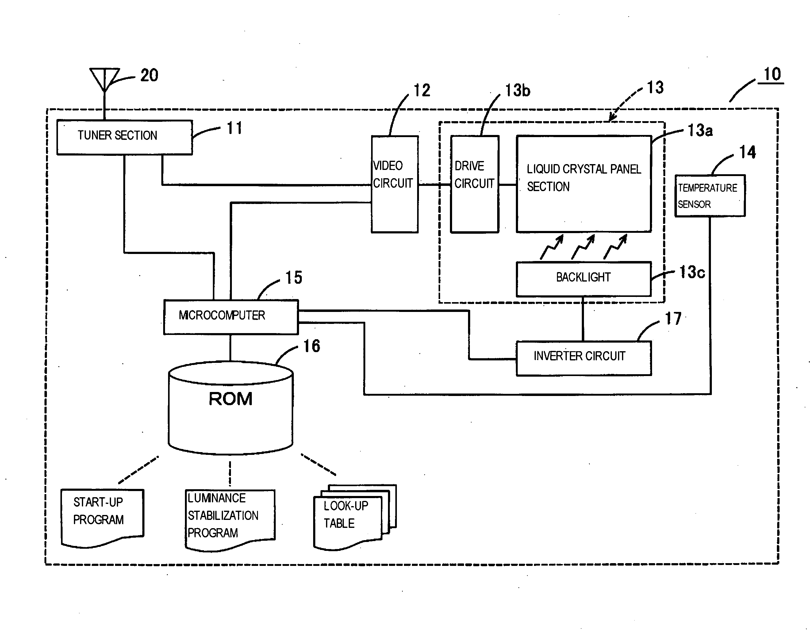
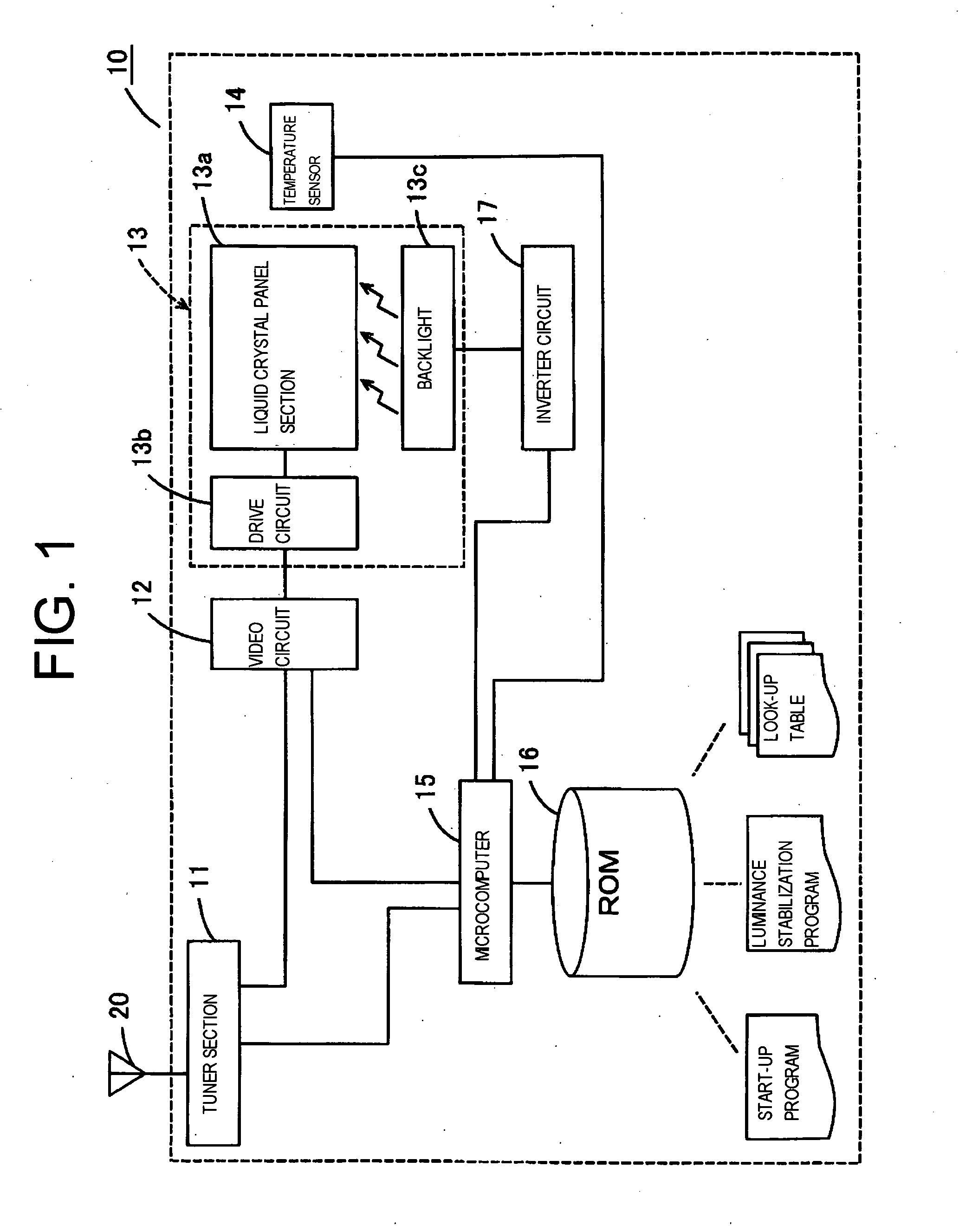
[0045]Hereinafter, a liquid crystal television as a first embodiment of the present invention will be explained with reference to FIGS. 1 through 5. FIG. 1 is a block configuration diagram of the liquid crystal television. The liquid crystal television 10 is for displaying pictures based on a video signal such as a television signal input therein. Therefore, the liquid crystal television 10 has a configuration including a tuner section 11 for extracting predetermined video signal and audio signal from the television broadcasting received by an antenna 20, a video circuit 12 (video signal processing unit) for executing a predetermined signal processing on the video signal received by the tuner 11, a liquid crystal display device 13 for displaying pictures based on the video signal from the video circuit 12, a microcomputer 15 for controlling the...


PUM


Abstract

A liquid crystal display device capable of correcting variation in luminance in a drive beginning period of the liquid crystal display device with a simple configuration by a microcomputer 15 referring to a luminance stabilization program and a look-up table recorded on a ROM 16 and executing contrast adjustment of the video signal by the video circuit 12 based on the look-up table, and a liquid crystal television using the liquid crystal display device are provided.

Description

CROSS-REFERENCES TO RELATED APPLICATIONS[0001]The entire disclosure of Japanese Patent Application No. 2007-193320, filed Jul. 25, 2007, is expressly incorporated herein by reference.BACKGROUND OF THE INVENTION[0002]1. Field of the Invention[0003]The present invention relates to a liquid crystal display device correcting the luminance of the screen, and in particular to a liquid crystal display device and a liquid crystal television using a backlight and correcting the luminance varied owing to the panel characteristic.[0004]2. Description of the Related Art[0005]FIG. 2 is a diagram showing the luminance of the screen in a predetermined period after the power is switched ON. According to the drawing, the luminance of an image displayed on the screen increases in a predetermined period of time after the power is switched ON, namely in a drive beginning period, along a gentle curve, and then, decreases gradually to be saturated in a constant level. Therefore, the luminance on the scre...

Claims


Application Information

Patent Timeline
Patent Type & Authority Applications(United States)
IPC IPC(8): G09G3/36
CPCG09G3/3406G09G3/3611G09G2320/041G09G2330/026G09G2320/0633G09G2320/066G09G2320/0626
Inventor URISU, TAKAYOSHI
Owner FUNAI ELECTRIC CO LTD
Why Eureka
Try Eureka