Structure of Exhaust Turbocharger Having Waste Gate Valve

a technology of exhaust turbocharger and waste gate valve, which is applied in the direction of liquid fuel engines, machines/engines, priming pumps, etc., can solve the problems of reducing the utilization of exhaust energy of engines, and achieve the effect of improving durability and reliability

Active Publication Date: 2009-01-29
MITSUBISHI HEAVY IND ENGINE & TURBOCHARGER LTD
View PDF9 Cites 30 Cited by
  • Summary
  • Abstract
  • Description
  • Claims
  • Application Information

AI Technical Summary

Benefits of technology

[0018]According to the invention, the plate-like valve body of the waste gate valve is formed such that the seat-side face thereof has a conical depression or constant-depth depression so that the seat-side face of the valve body does not contact the end face of the partition wall partitioning the bypass passages, or the plate-like valve body is formed such that the seat-side face thereof is a flat surface and a depression is formed on the end face of the partition wall so that the seat-side face of the valve body does not contact the end face of the partition wall over the length or a central region of the end face of the partition wall when the waste gate valve closes the bypass passages by allowing the seat face of valve body to seat against the seat face of the of the turbine housing at the outlet end of the bypass passages. Therefore, occurrence of swing of the valve body with the extending line of end face (which tends to be protruded from the annular seat face when machining the seat face of the turbine housing at the outlet end of the bypass passages including the annular seat face and the end face of the partition wall) of the partition wall as a fulcrum axis of swing can

Problems solved by technology

Further, exhaust gas leak through the clearance between the seat face 11c of the valve body 11 and the annular

Method used


Image

  • Structure of Exhaust Turbocharger Having Waste Gate Valve
  • Structure of Exhaust Turbocharger Having Waste Gate Valve
  • Structure of Exhaust Turbocharger Having Waste Gate Valve

Examples


first embodiment

The First Embodiment

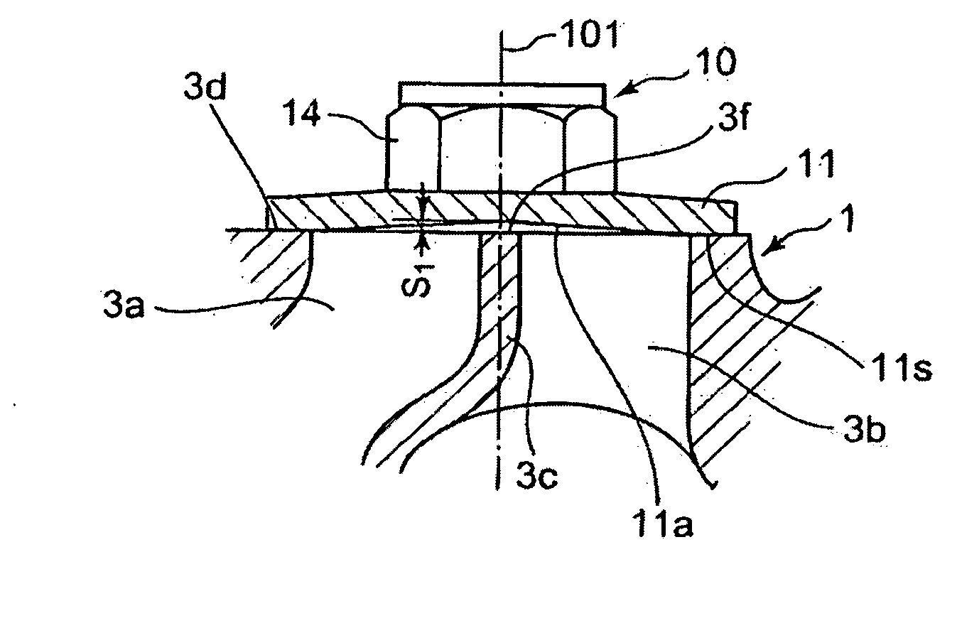
[0039]FIG. 1 is a partial cross sectional view around the waste gate valve of a first embodiment (enlarged sectional view of Z part in FIG. 6).

[0040]Referring to FIG. 1, a waste gate valve 10 comprises a plate-like valve body 11 for opening / closing a pair of two exhaust gas bypass passages 3a and 3b, a lever 12 (see FIG. 5) connected to the valve body 11, a nut 14 for fastening the valve body 11 to the lever 12, a connecting arm 13 (see FIG. 5). The waste gate valve 10 is composed such that the exhaust gas bypass passages 3a and 3b are closed or opened by allowing the seat face 11s of the valve body 11 at the peripheral part thereof to be seated against the seat face 3d of the turbine housing 1 at the peripheral part of the opening end of the pair of the exhaust gas bypass passages 3a and 3b or to be departed from the seat face 3d via the lever 12 and connecting arm 13.

[0041]The valve body 11 is formed such that its seat-side face of which the peripheral part ser...

second embodiment

The Second Embodiment

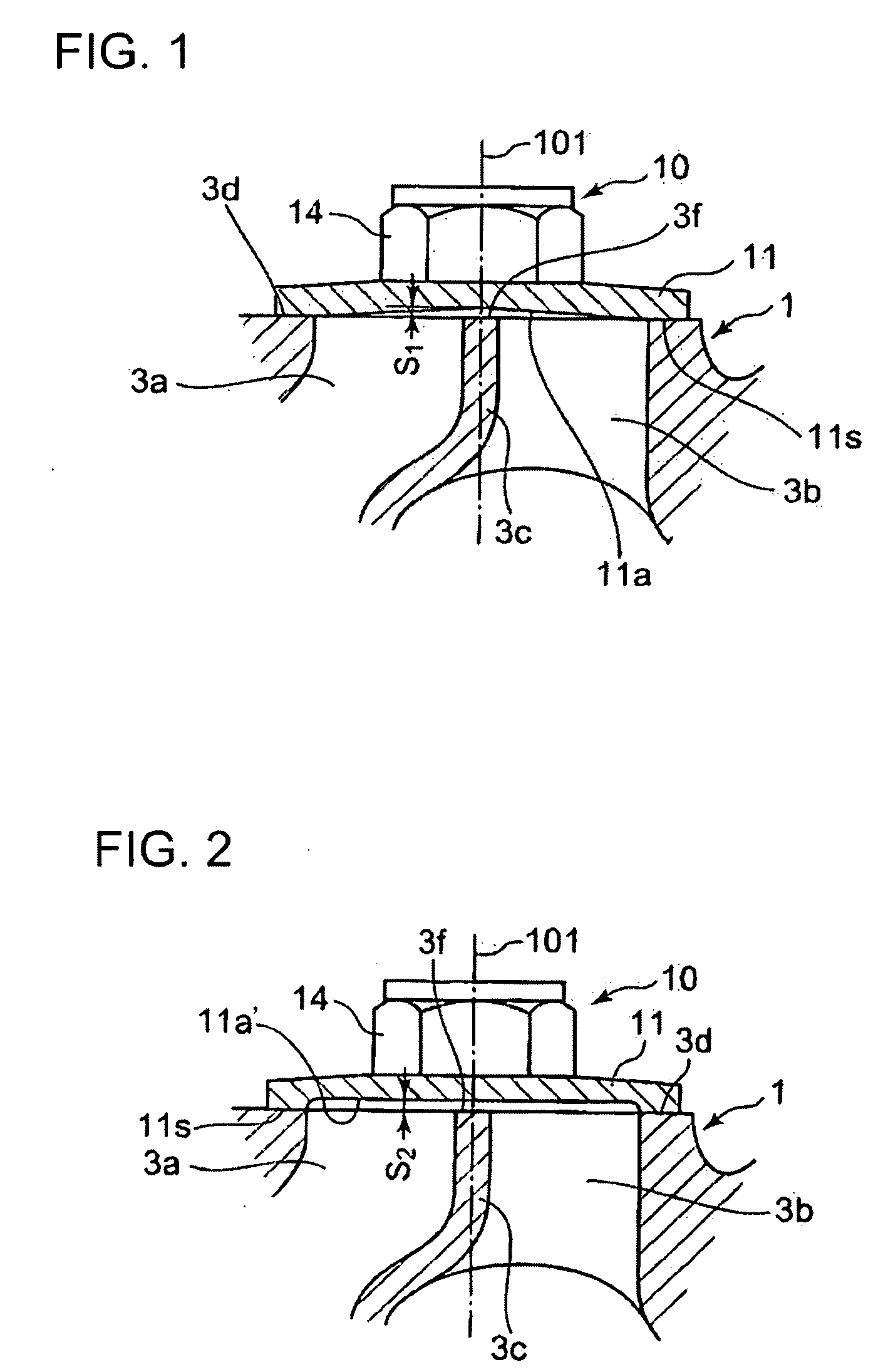
[0042]FIG. 2 is a view as in FIG. 1 of a second embodiment.

[0043]In the second embodiment, the valve body 11 is formed such that its seat-side face has an annular seat face 11s and a circular depression 11a′ of a constant depth S2 radially inside the annular seat face 11s. The circular depression 11a′ is formed so that the seat-side face of the valve body 11 does not contact the end face 3f of the partition wall 3c when the valve body 11 seats against the seat face 3d of the turbine housing 1 to close the bypass passages 3a and 3b.

[0044]Other than that is the same as the first embodiment and the same constituent parts are denoted by the same reference numerals.

third embodiment

The Third Embodiment

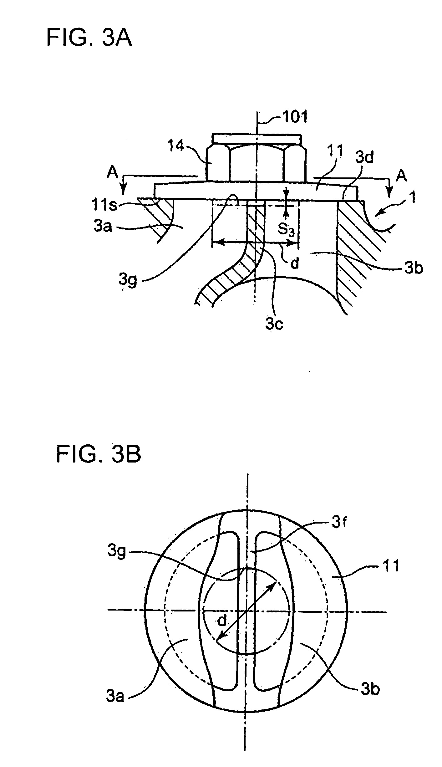
[0045]FIG. 3A is a view as in FIG. 1 of a third embodiment, and FIG. 3B is a view in the direction of arrow A-A of FIG. 3A.

[0046]In the third embodiment, a depression 3g of depth S3 is formed to the end face 3f the partition wall 3c. The depression 3g may be formed by milling with an end mill of diameter ‘d’ with its center line coinciding with the center line 101 of the waste gate valve 10. The diameter ‘d’ may be equal to or smaller than the diameter of a circle formed by the circumferences of semi-circles forming the openings of the two bypass passages at the outlet thereof opening into the exhaust gas outlet passage 8. Therefore, the depression 3g is an elongate depression of depth S3 formed on the end face 3f of the partition wall 3c. The valve body 11 is formed such that its seat-side face is a flat surface of which the peripheral part serves as the seat face 11s of the valve body 11.

[0047]Therefore, the seat-side face of the valve body does not contact the...


PUM


Abstract

An exhaust turbocharger is provided which is enhanced in durability and reliability by making the valve body of the waste gate valve to contact uniformly the seat face of the turbine housing at the opening of two exhaust gas bypass passages without affected by the end face of the partition wall partitioning the two bypass passages, thereby preventing generation of vibration and vibration sound (chattering) of the valve body and occurrence of gas leakage due to defective seating of the valve body against the seat face of the turbine housing. The turbocharger has a twin scroll type turbine housing having two exhaust gas entrance channels and two exhaust gas bypass passages for allowing exhaust gas entered the turbine housing to bypass the turbine rotor and being equipped with a waste gate valve for opening/closing the two exhaust gas bypass passages by allowing a plate-like valve body to seat against and depart from a seat face at an outlet end side of the two bypass passages, wherein a depression is formed to a seat-side face of the valve body or to the end face of the partition wall so that the seat-side face of the valve body does not contact the end face of the partition wall at least in the central region of the end face of the partition wall when the valve body seats against the seat face at the outlet end side of the bypass passages.

Description

TECHNICAL FIELD[0001]The present invention relates to structure of an exhaust turbocharger having a twin scroll type turbine housing which has two exhaust gas entrance channels and being equipped with a waste gate valve.BACKGROUND ART[0002]Exhaust turbochargers for pressurizing charging air of engines by utilizing exhaust gas energy of the engines, especially those used in engines for automobiles are equipped with waste gate valves, which allows a part of exhaust gas from the engine to bypass the turbine of the exhaust turbocharger from the entrance passage to the outlet passage of the turbine housing via a bypass passage by opening the waste gate valve for opening / closing the bypass passage so that exhaust gas energy imparted to the turbine rotor is reduced in order to prevent excessive increase of charging air pressure.[0003]FIGS. 4 to 7 show an example of a twin scroll type exhaust turbocharger having a waste gate valve disclosed for example in Japanese Laid-Open Patent Applicati...

Claims


Application Information

Patent Timeline
IPC IPC(8): F02B37/18F02B37/22
CPCF01D17/105F02B37/025F02B37/18F05D2220/40F02B39/00Y02T10/144F02B37/183Y02T10/12
Inventor NAEMURA, KAZUOMIURA, YOSHIMITSU
Owner MITSUBISHI HEAVY IND ENGINE & TURBOCHARGER LTD
Why Eureka
Try Eureka