High performance coaxial connector

a coaxial connector, high-performance technology, applied in the direction of coupling devices, two-part coupling devices, electrical devices, etc., can solve the problems of complex coaxial connector design, high manufacturing cost, complex production of multi-component connectors, etc., to achieve the effect of improving electrical performan

Inactive Publication Date: 2009-01-29
TE CONNECTIVITY CORP
View PDF13 Cites 126 Cited by
  • Summary
  • Abstract
  • Description
  • Claims
  • Application Information

AI Technical Summary

Benefits of technology

[0008]The forward cylindrical section includes barbs for securing the dielectric therewithin. The forward cylindrical section also has forward extending tines. The shell further includes flaps configured to partially cover the slots. The rear edge of the collar is formed by folding collar tabs. The dielectric includes an axial through hole configured to receive a conductive pin. The connector is configured to provide enhanced electrical performance greater than or equal to 4 GHz.
[0010]The assembly further includes a crimping sleeve to attach a coaxial cable to the crimp section. The forward cylindrical section has barbs for securing the dielectric therewithin. The forward cylindrical section also has forward extending tines. The shell has flaps configured to partially cover the slots and a rear edge formed by folding tabs of the collar. The connector is configured to provide enhanced electrical performance greater than or equal to 4 GHz.
[0012]The method further includes disposing a dielectric within the receiving portion of the inner conductive housing. The method additionally includes attaching a conductive pin to a center wire of a coaxial cable, inserting the conductive pin into a through hole of the dielectric, and crimping a locking mechanism around the coaxial cable to secure the coaxial cable to the crimping portion of the shell. The dielectric is secured within the receiving portion of the inner conductor by barbs formed into the front receiving section of the inner conductive housing. The connector is configured to provide enhanced electrical performance greater than or equal to 4 GHz.

Problems solved by technology

Past coaxial connector designs have been complex and have utilized costly manufacturing procedures.
In the prior art, many coaxial connector designs have been proposed, but all fail to provide a simple construction having a small number of components.
These multi-component connectors are complex to produce.
Additionally, these past connectors have failed to provide enhanced electrical performance characteristics.

Method used


Image

  • High performance coaxial connector
  • High performance coaxial connector
  • High performance coaxial connector

Examples


Embodiment Construction

[0028]The present invention now will be described more fully hereinafter with reference to the accompanying drawing, in which a preferred embodiment of the invention is shown. This invention may, however, be embodied in many different forms and should not be construed as limited to the embodiments set forth herein; rather, these embodiments are provided so that this disclosure will be thorough and complete and will fully convey the scope of the invention to those skilled in the art.

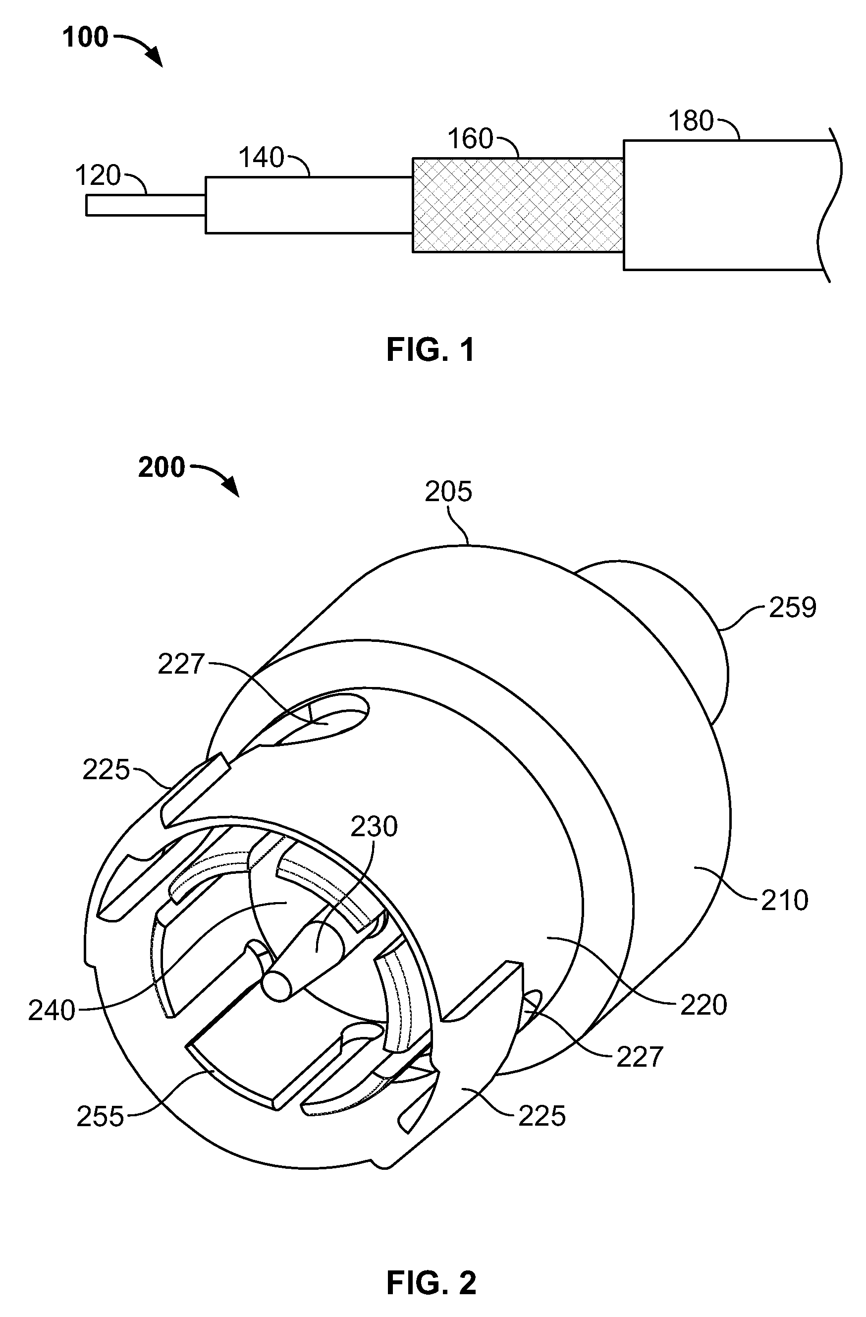
[0029]With initial reference to FIG. 1, an exemplary coaxial cable 100 is shown with various layers stripped to expose an electrically conductive center wire 120. A dielectric sheathing 140 surrounds the center wire 120. A flexible, electrically conductive metallic braid, commonly referred to as a ground shield 160, surrounds the dielectric sheathing 140. Finally, a synthetic plastic dielectric outer sheathing 180 surrounds the ground shield 160.

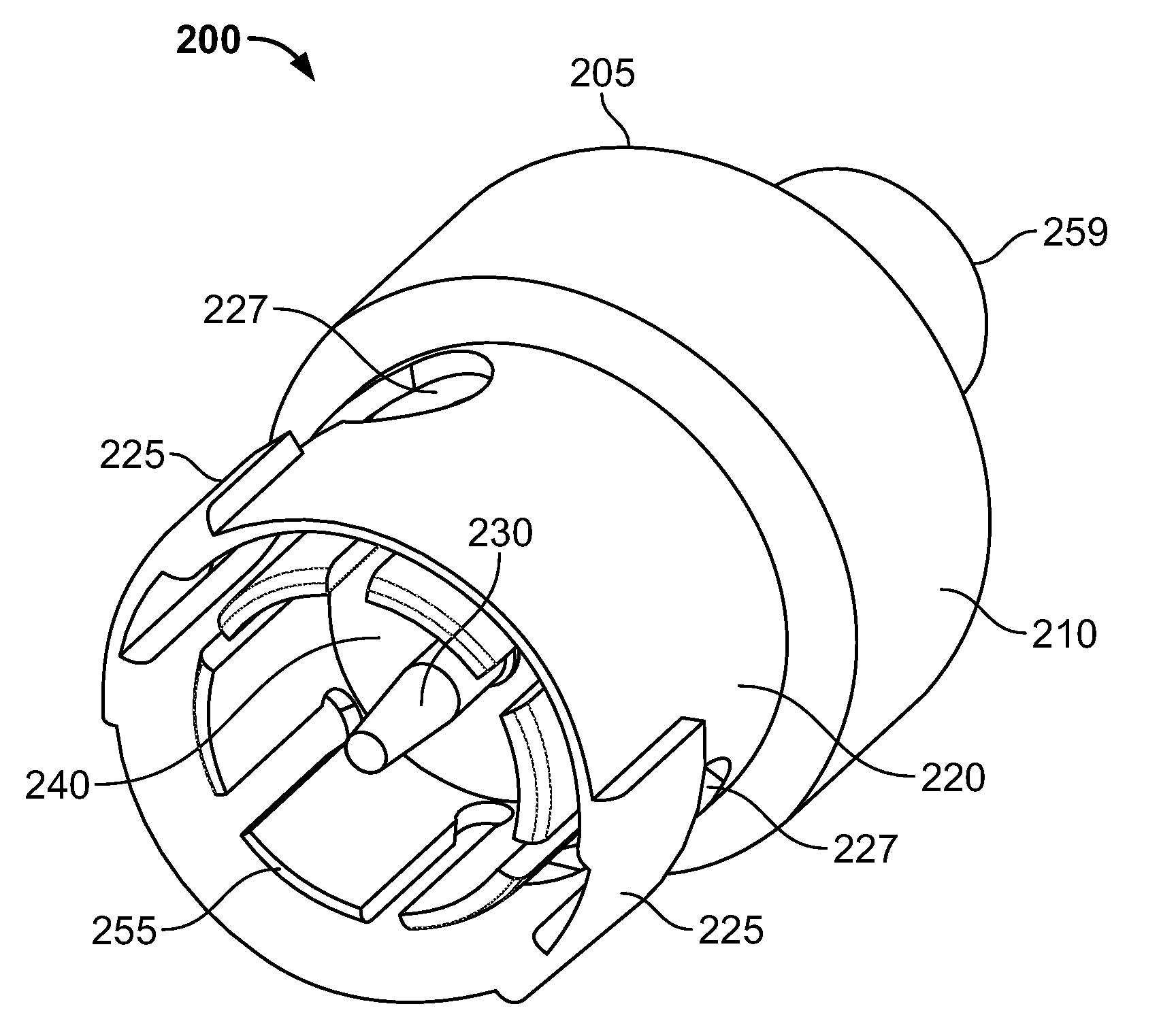
[0030]Referring to FIG. 2, an exemplary embodiment of a coax...


PUM


Abstract

A high performance coaxial connector used to terminate a coaxial cable and provide an electrical connection to a mating coaxial connector is disclosed. The coaxial connector is formed with few individual parts and may be configured to provide enhanced electrical performance greater than or equal to 4 GHz.

Description

FIELD OF THE INVENTION[0001]The present invention relates to coaxial cable connectors. More specifically, the present relates to a coaxial connector and method of manufacture.BACKGROUND OF THE INVENTION[0002]Coaxial cable connectors are commonly used to terminate coaxial cables and provide an electrical connection to a mating coaxial cable connector. The male coaxial connector includes a metallic housing having a cylindrical sleeve. Centrally disposed within the sleeve is a center contact pin. The center contact pin is maintained in coaxial alignment within the sleeve by means of an optimized dielectric.[0003]Past coaxial connector designs have been complex and have utilized costly manufacturing procedures. The individual parts may be machined or die cast. The assembly often has required several hand assembly steps to form the final connector. Therefore, a need exists to provide an inexpensive yet high performance coaxial connector that requires minimal assembly steps.[0004]Furtherm...

Claims


Application Information

Patent Timeline
Patent Type & Authority Applications(United States)
IPC IPC(8): H01R9/05
CPCH01R9/0518H01R2103/00H01R24/40
Inventor SYKES, MICHAEL T.WEIDNER, KEVIN E.CONNER, TROY E.
Owner TE CONNECTIVITY CORP
Why Eureka
Try Eureka