Sensor mounting system

a technology of mounting system and sensor, which is applied in the field of holding a sensing device, can solve the problems of limiting the stretching that can lead to electrical measurement artifacts, and achieve the effects of limiting the stretching, accurate specification, and higher level of fidelity

Active Publication Date: 2009-01-29
QUANTUM APPLIED SCI & RES
View PDF17 Cites 60 Cited by
  • Summary
  • Abstract
  • Description
  • Claims
  • Application Information

AI Technical Summary

Benefits of technology

[0016]The height of the mount, the mean length of the compression element and the force applied by the compression element at its mean level of compression are all set in advance. Thus, a particular feature of the present invention is that the sensor contact pressure can be accurately specified for the particular part of the body with which the sensor is to be in contact and for the particular range of expected subject activities. This control enables the trade-off between sensor comfort and sensor performance to be optimized and set in advance to a much higher level of fidelity than has previously been possible.
[0017]In one preferred embodiment, the sensor is a biopotential sensor that utilizes a dry electrode. The compression element provides a nearly constant force that holds the electrode against the skin of the subject. Friction where the mount contacts the subject mechanically stabilizes the region of skin or scalp that is enclosed within the footprint of the mount, limiting the stretching that can lead to electrical measurement artifacts. The sensor is held against the scalp by a biasing force that is preset depending on the duration it is to be worn and the level of physical activity expected. Optionally, the surface of the sensor includes fingers that fit between strands of hair, thereby allowing a good contact on subjects with a large amount of hair.

Problems solved by technology

Friction where the mount contacts the subject mechanically stabilizes the region of skin or scalp that is enclosed within the footprint of the mount, limiting the stretching that can lead to electrical measurement artifacts.

Method used


Image

  • Sensor mounting system
  • Sensor mounting system
  • Sensor mounting system

Examples


Embodiment Construction

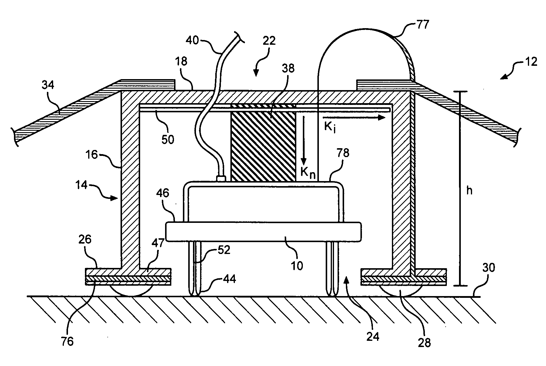
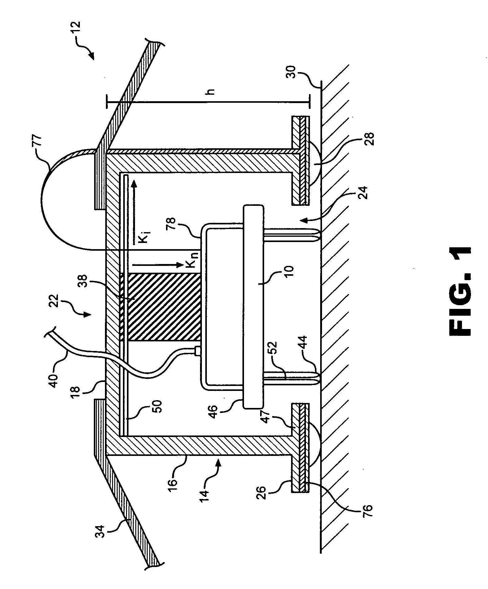
[0027]With initial reference to FIG. 1, a sensor mounting system for optimally coupling a sensor 10 to a living subject is shown and generally designated 12. Mounting system 12 includes a main body portion 14 having at least one side wall 16 and a top wall 18, which together define a housing 22 having an opening 24. In a preferred embodiment, main body portion 14 is in the form of a short cylinder including extension stops 26 extending therefrom and having an interface layer 28 that forms the predominant contact to a surface 30 (i.e., skin) of a living subject. A secondary support structure 34 provides a mechanical force that holds mounting system 12 to surface 30. Secondary support structure 34 can be straps, or other means might be used, such as a spring arm or an item of clothing for supporting and positioning mounting system 12. Further, the connection between main body portion 14 and secondary support structure 34 can be made at two fixed points, as shown in FIG. 1, at three or...


PUM


Abstract

A sensor mounting system includes a rigid main body portion defining a housing within which is mounted a compression element. In use, the compression element provides a predetermined biasing force to force a sensor against the skin of a subject. A secondary support structure provides an adjustable biasing force to retain the main body portion against the subject. Alternatively, the main body portion may be mounted to a rigid pod with one or more secondary compression elements, with the pod itself retained against the subject. An interface layer extending from the main body portion provides a cushion to improve the comfort of the subject. The interface layer and sensor interface elements may be in the form of fingers to increase contact of the sensor with a selected portion of the subject.

Description

CROSS-REFERENCE TO RELATED APPLICATIONS[0001]The present application claims the benefit of U.S. Provisional Patent Application Ser. No. 60 / 924,638 entitled “Wearable Bioelectrode” filed May 23, 2007.STATEMENT REGARDING FEDERALLY SPONSORED RESEARCH AND DEVELOPMENT[0002]This invention was made and developed under Contract No. W91ZKL-04-P-0235 awarded by the Army Phase I and II SBIR. The Government has a fully paid up non-exclusive license in this invention.BACKGROUND OF THE INVENTION[0003]The present invention generally pertains to holding a sensing device against a person or animal. More particularly, the present invention pertains to sensing devices for which the performance depends at least partly on the contact pressure of the device to the body. The present invention is particularly, but not exclusively, useful for long duration measurement of biopotentials on the skin.[0004]There are many current and emerging technologies that require contact between a sensing device and a livin...

Claims


Application Information

Patent Timeline
Patent Type & Authority Applications(United States)
IPC IPC(8): A61B5/04
CPCA61B5/6843A61B5/04A61B5/24
Inventor MATTHEWS, ROBERTMCDONALD, NEIL JOHN
Owner QUANTUM APPLIED SCI & RES
Why Eureka
Try Eureka