Operating mechanism, medical manipulator, and surgical robot system

Inactive Publication Date: 2009-01-29
TERUMO KK
View PDF25 Cites 151 Cited by
  • Summary
  • Abstract
  • Description
  • Claims
  • Application Information

AI Technical Summary

Benefits of technology

[0034]At least one angularly movable mechanism of the distal-end working unit, which is rotatable about the axis not parallel to the shaft, allows the distal-end working unit to make more complex motions. However, when the distal-end working unit remains not parallel to the axis of the shaft, the attitude of the angularly movable mechanism needs to be chan

Problems solved by technology

However, they may not necessarily be suitable to open and close a gripper or scissors with delicate movements.
However, the rolling mechanism may have its angular displacement difficult to recognize.
However, if the distal-end working unit operated by one or more of the angularly m

Method used


Image

  • Operating mechanism, medical manipulator, and surgical robot system
  • Operating mechanism, medical manipulator, and surgical robot system
  • Operating mechanism, medical manipulator, and surgical robot system

Examples


Example

[0053]Operating mechanisms, medical manipulators, and surgical robot systems according to embodiments of the present invention will be described below with reference to FIGS. 1 through 17 of the accompanying drawings.

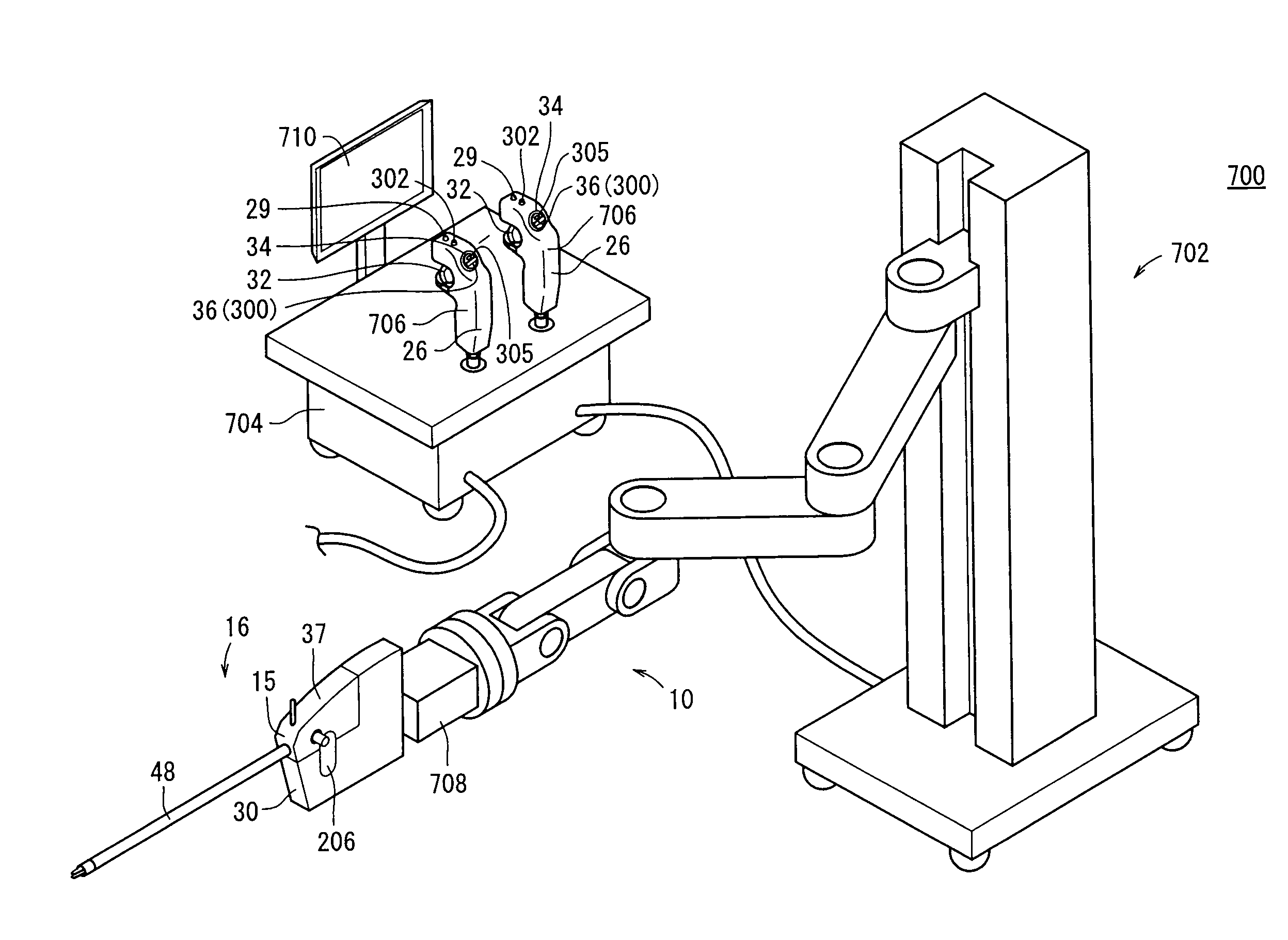
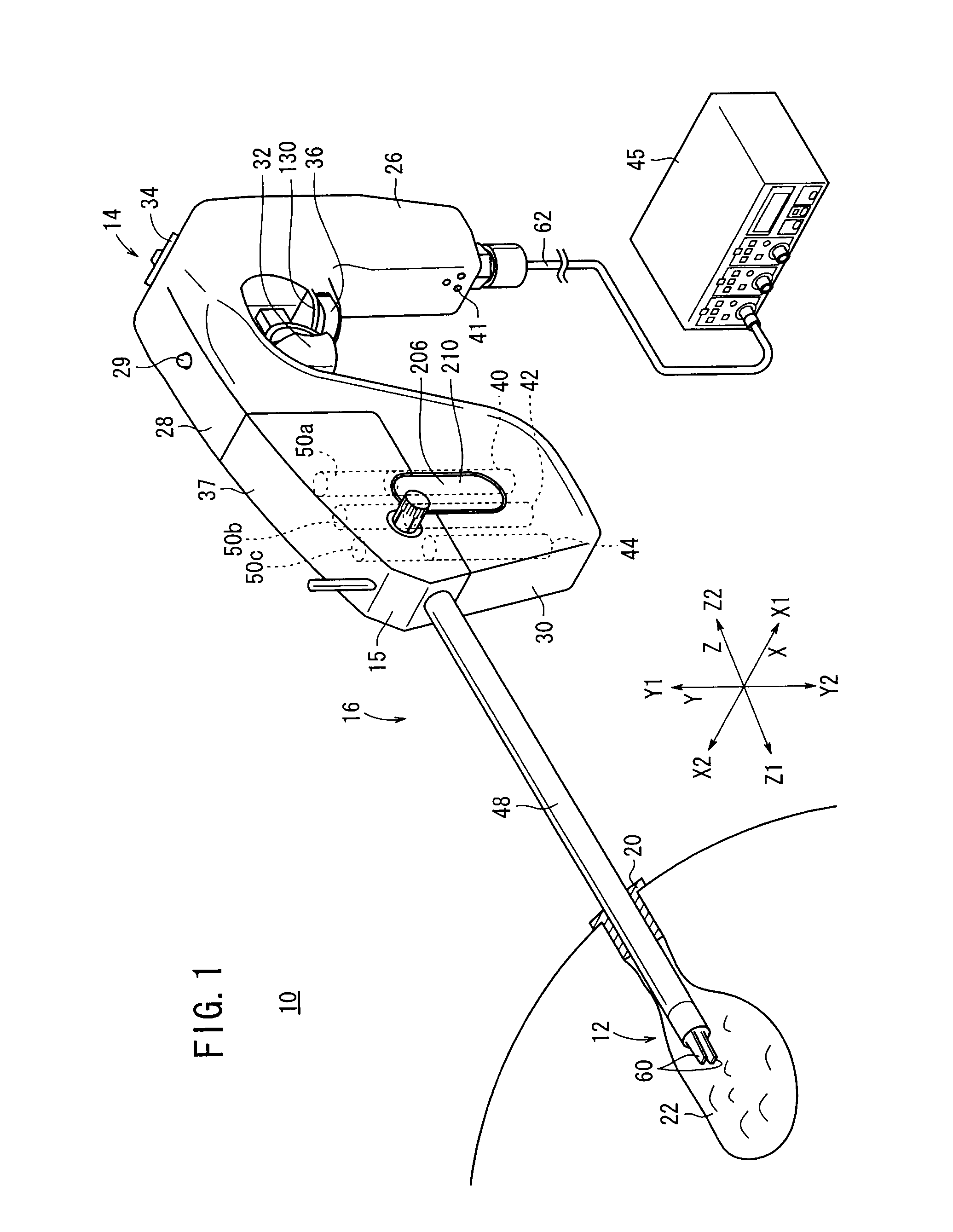
[0054]A manipulator 10 (see FIG. 1) has a distal-end working unit 12 for gripping a portion of a living tissue, a curved needle, or the like for performing a certain surgical treatment, and is usually referred to as gripping forceps or a needle driver (needle holder).

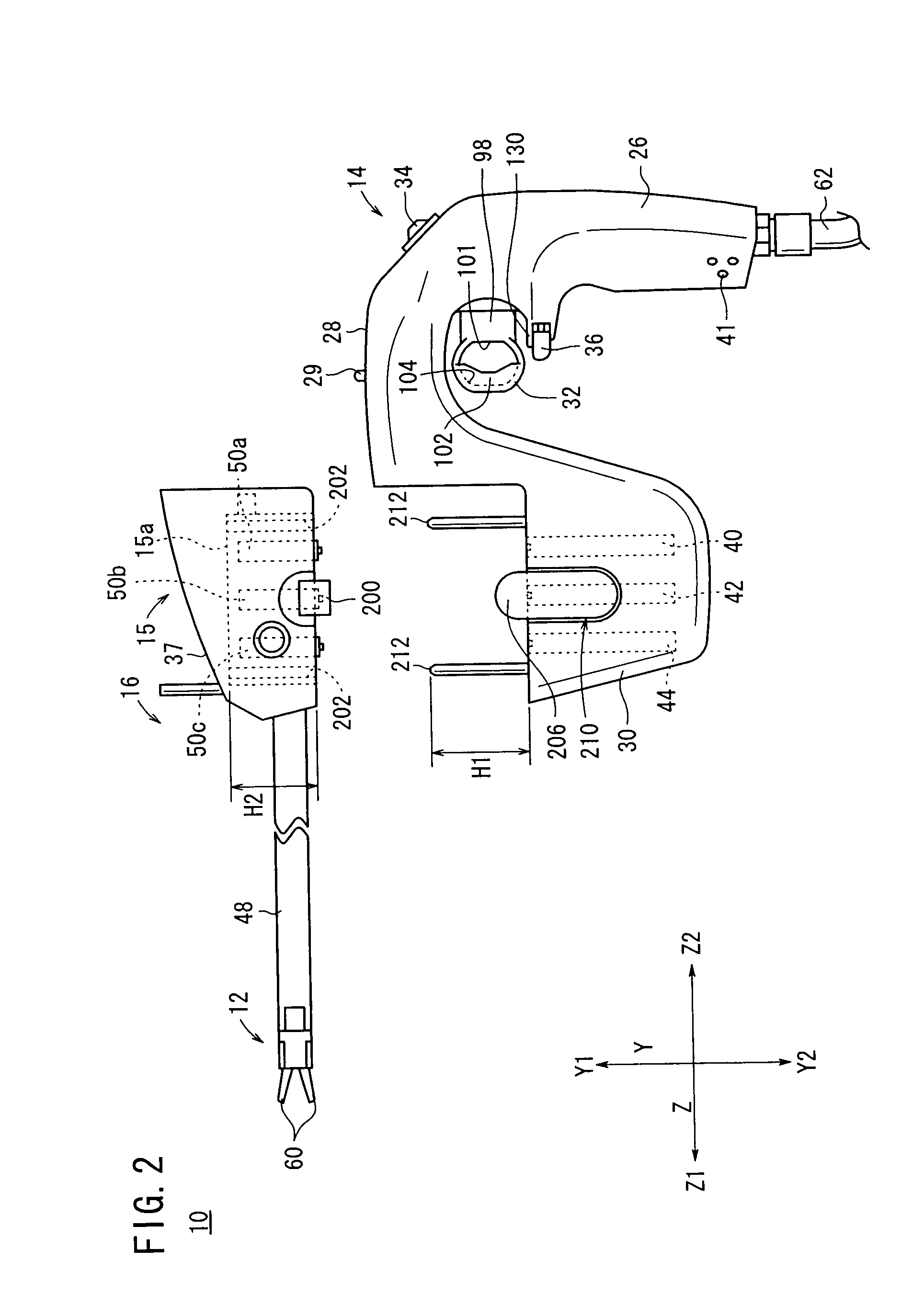
[0055]As shown in FIGS. 1 and 2, the manipulator 10 comprises an operation command unit (operating mechanism) 14 on a proximal end portion which is held and operated by hand and a working unit 16 detachably mounted on the operation command unit 14.

[0056]It shall be assumed in the following description that, as shown in FIG. 1, the transverse directions are defined as X directions, the vertical directions as Y directions, and the longitudinal directions of a hollow joint shaft 48 as Z directions. Further, am...


PUM


Abstract

A medical manipulator includes an operation command unit having motors and a working unit detachably mounted on the operation command unit. The operation command unit includes a grip handle for being gripped by a human hand, and a trigger lever movable toward and away from the grip handle. The trigger lever comprises a pulling member which can be pulled toward the grip handle by a finger held against the pulling member, and a pushing member which can be pushed away from the grip handle by the finger held against the pushing member, the pushing member being disposed in facing relation to the pulling member. The pushing member has a hemispherical cavity defined in a surface thereof which faces the pulling member.

Description

BACKGROUND OF THE INVENTION[0001]1. Field of the Invention[0002]The present invention relates to an operating mechanism having a grip handle to be gripped by hand, a medical manipulator and a surgical robot system which are operable by such an operating mechanism.[0003]2. Description of the Related Art[0004]In laparoscopic surgery, a number of small holes are opened in a patient's abdomen or the like, and an endoscope, a forceps (or manipulator) or the like is inserted, and surgery is carried out while the surgeon observes an image from the endoscope on a monitor. In this type of laparoscopic surgery, owing to the fact that opening of the abdominal cavity is unnecessary, the burden on the patient is small, and the number of days required for the post-operative recovery and the number of days spent in the hospital can be significantly reduced. Therefore, laparoscopic surgical operations are expected to find an increased range of applications.[0005]As disclosed in Japanese Laid-Open P...

Claims


Application Information

Patent Timeline
IPC IPC(8): A61B17/00
CPCA61B19/22A61B19/2203A61B2017/00367A61B2017/00438A61B2017/0046A61B2017/00477A61B2017/2925A61B2019/2223A61B2019/2276A61B2017/00398A61B2017/2911A61B34/30A61B34/37A61B34/70A61B2034/742
Inventor OMORI, SHIGERUUENOHARA, SHUICHISANO, HIROAKI
Owner TERUMO KK
Why Eureka
Try Eureka