System for controlled prosthesis deployment

Inactive Publication Date: 2009-01-29
ABBOTT LAB VASCULAR ENTERPRISE
View PDF18 Cites 65 Cited by
  • Summary
  • Abstract
  • Description
  • Claims
  • Application Information

AI Technical Summary

Benefits of technology

[0008]In a more detailed aspect of the invention, at least one of the portions of the opening extending generally parallel to the axis of the base member includes a curved portion. The curved portion may have a single curvature, or it may have a double curvature. In another detailed aspect, at least one of the portions of the opening extending generally perpendicular to the axis of the base member includes a curved portion. The curved portions are configured to slow down the longitudinal movement of the slide member under the urging of the biasing member, to avoid damage to the system.
[0009]In another aspect, the invention includes a method of retracting a sheath to uncover a prosthesis mounted on a catheter. This aspect includes attaching the catheter to a base member having a first elongate axis, and operably attaching the sheath to a slide member having a second elongate axis, the slide member being slidab

Problems solved by technology

Although devices exist in the art for retracting an outer sheath from its position surrounding a prosthesis loaded onto a catheter, these are typically complex and expensive to manufacture, and tend to have little or no safeguard to prevent accidental instantane

Method used


Image

  • System for controlled prosthesis deployment
  • System for controlled prosthesis deployment
  • System for controlled prosthesis deployment

Examples


Embodiment Construction

[0018]With reference to the drawings, which are provided by way of exemplification and not limitation, there is described a controlled prosthesis deployment system having features of the present invention.

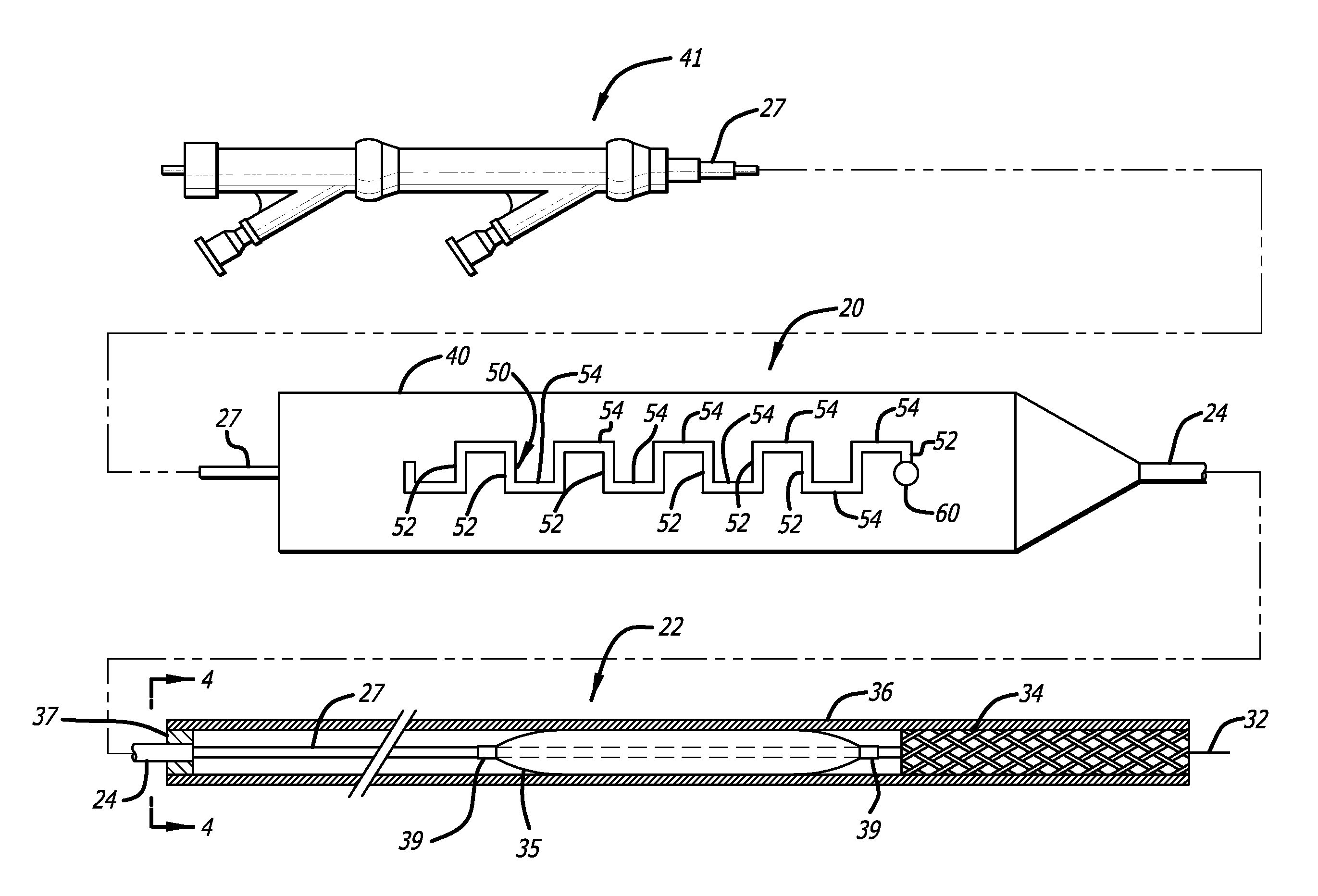
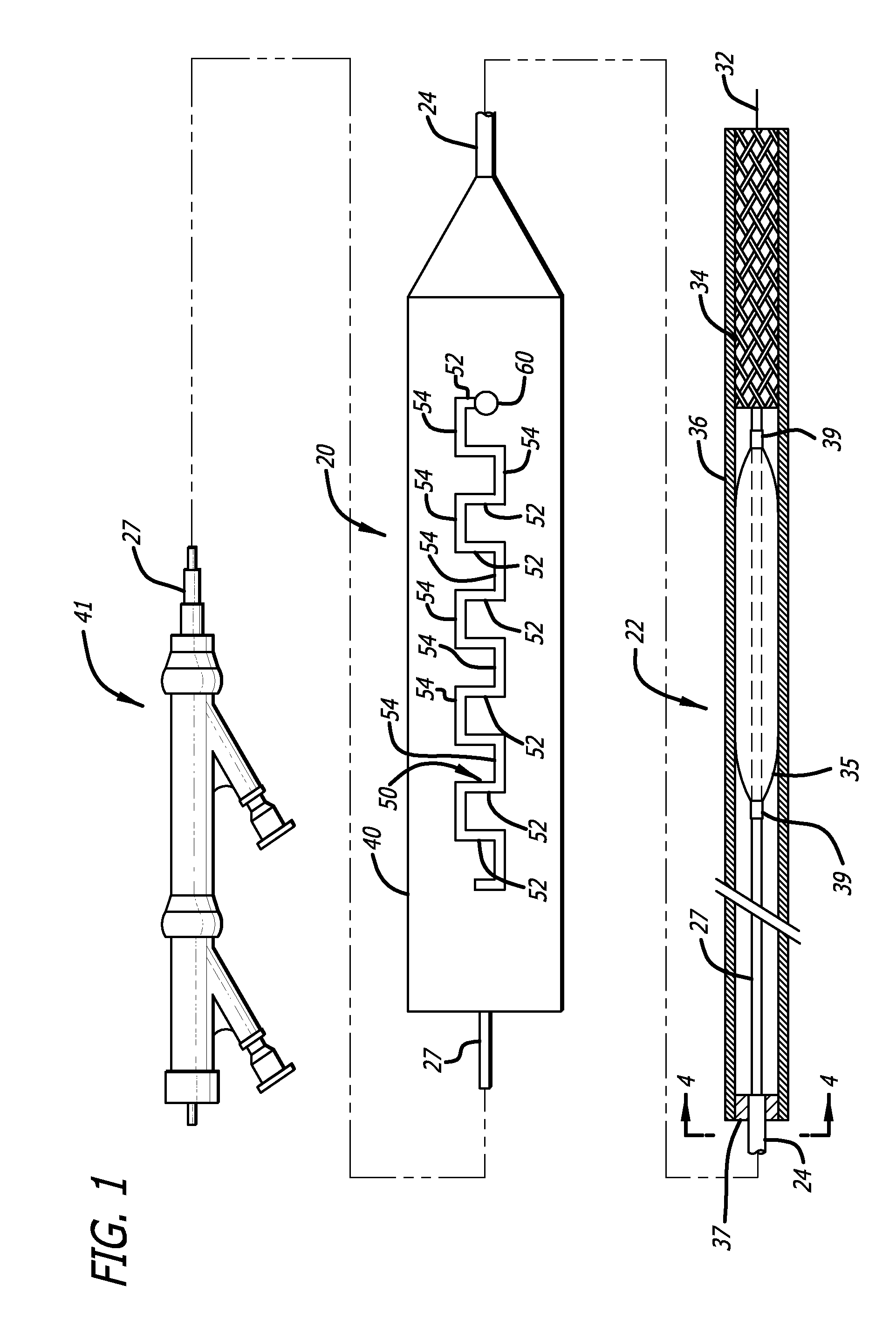
[0019]A preferred embodiment of the invention includes a release handle, generally identified by the numeral 20. The release handle is adapted to operate in conjunction with a catheter 22. The catheter is configured to remotely deliver a prosthesis in a body vessel or duct.

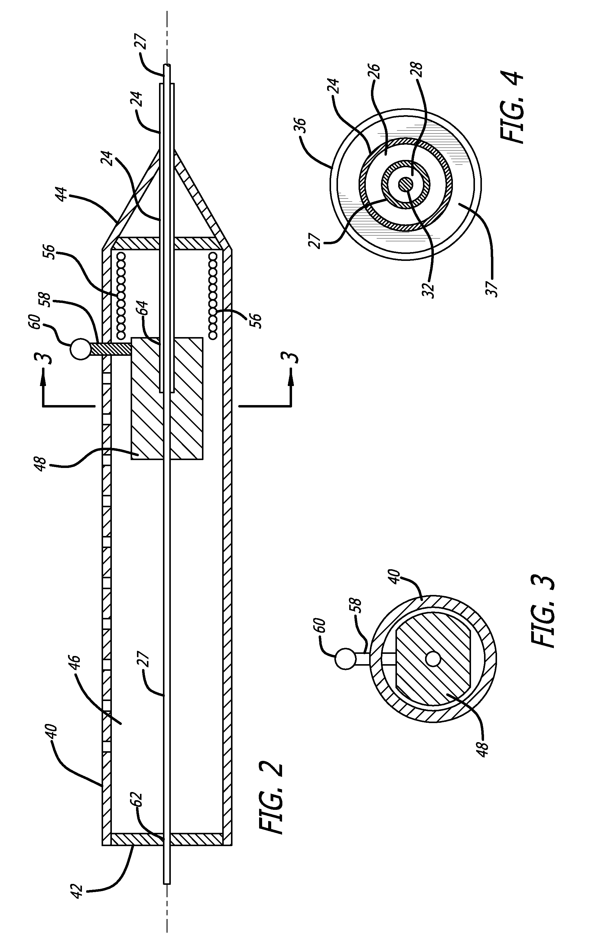
[0020]Catheters for remotely delivering a prosthesis are known, and may include a core cylinder 27 having an internal lumen 28 (FIG. 4). A guidewire 32 may be inserted within the lumen 28, according to known usage wherein the guidewire is first threaded into a body vessel (not shown), whereafter the catheter 22 is run up into the body vessel over the guidewire 32. At the distal end of the catheter, a prosthesis may be positioned to surround the catheter. In FIG. I it is shown that the prosthesis may be a self-exp...


PUM


Abstract

A system for controlled deployment of a prosthesis, in which a sheath is retracted from a prosthesis in a body vessel or duct. The system includes a handle for deploying the prosthesis, the handle comprises a base member fixed to a catheter, and a slide member for sliding past the base member, the slide member being attached to an end of a retraction member. The base member includes an opening having the general shape of a rectangular wave for interacting with the slide member, whereby, repeated manipulation of the slide member causes the sheath to be retracted.

Description

BACKGROUND OF THE INVENTION[0001]The present invention relates to an implant delivery and deployment system. More specifically, the invention relates to a deployment system that uses a handle operable under automatically controlled conditions to withdraw the retractable outer sheath and deploy a medical implant for minimally invasive application, such as an endovascular stent graft, vena cava filter, self-expanding stent, balloon expandable stent, and the like.[0002]Delivery systems for deploying a medical implant, such as an endovascular stent graft, vena cava filter, self-expanding stent, balloon expandable stent or the like, are known in the field of medical technology. These medical devices have many uses and applications. In particular, a stent is a prosthesis or implant which is generally tubular with openings formed therein, and which is expanded radially in a vessel or lumen to improve and reinforce the vessel's patency. Stents are widely used in body lumens, body canals, du...

Claims


Application Information

Patent Timeline
IPC IPC(8): A61F2/84
CPCA61F2/95A61F2002/9517A61F2/958A61F2/9517
Inventor KOCH, INA
Owner ABBOTT LAB VASCULAR ENTERPRISE
Why Eureka
Try Eureka