
Axially nested slide and lock expandable device

Inactive Publication Date: 2009-01-29
REVA MEDICAL
View PDF41 Cites 89 Cited by
  • Summary
  • Abstract
  • Description
  • Claims
  • Application Information

AI Technical Summary

Benefits of technology

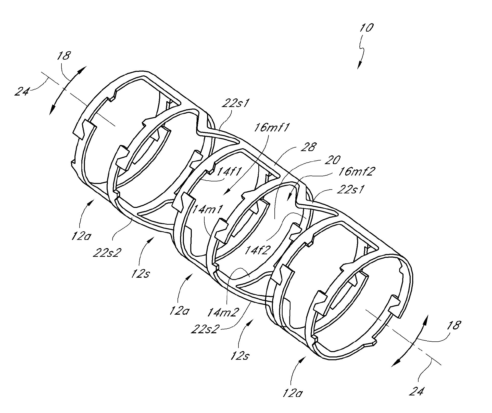
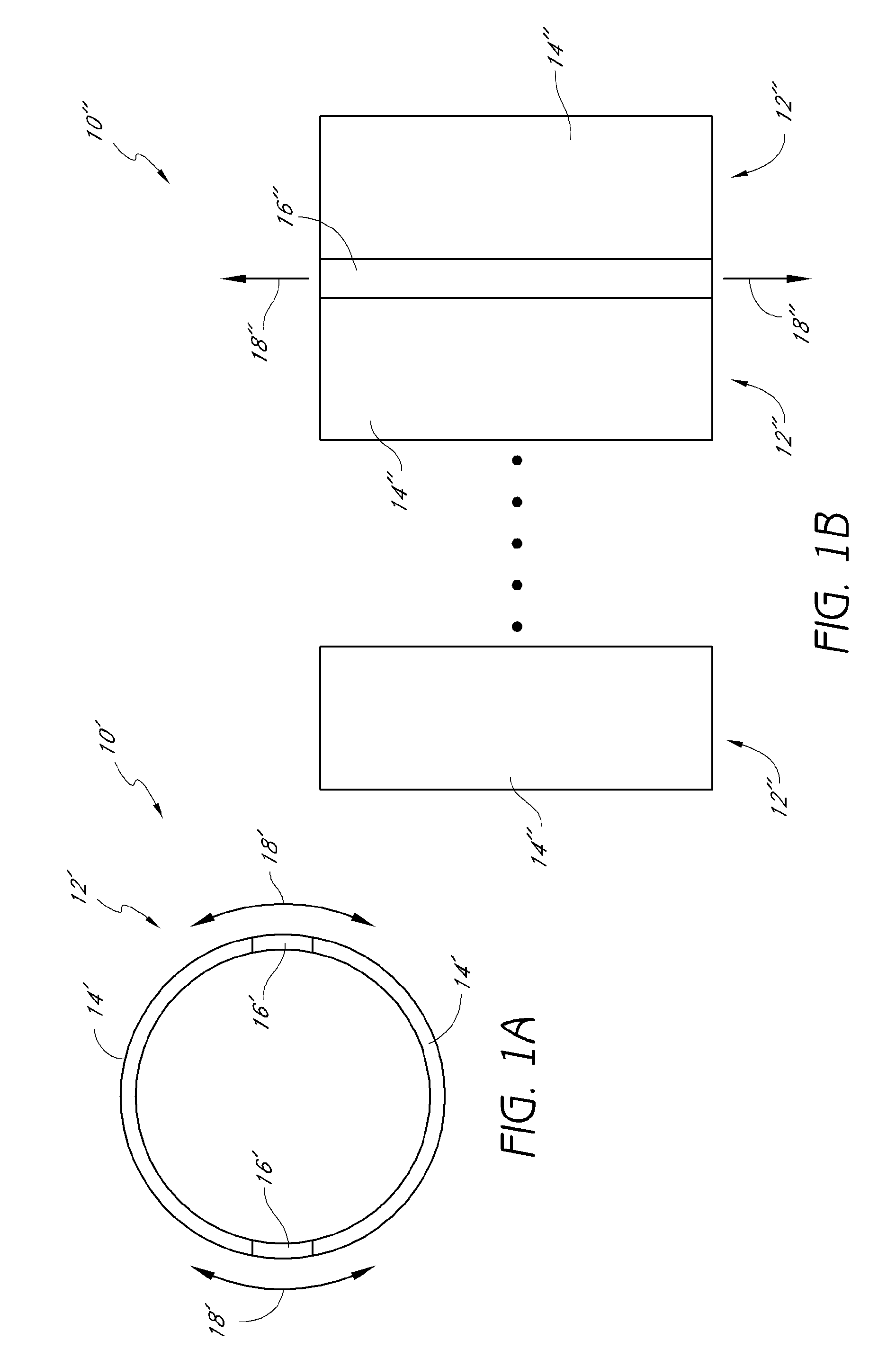
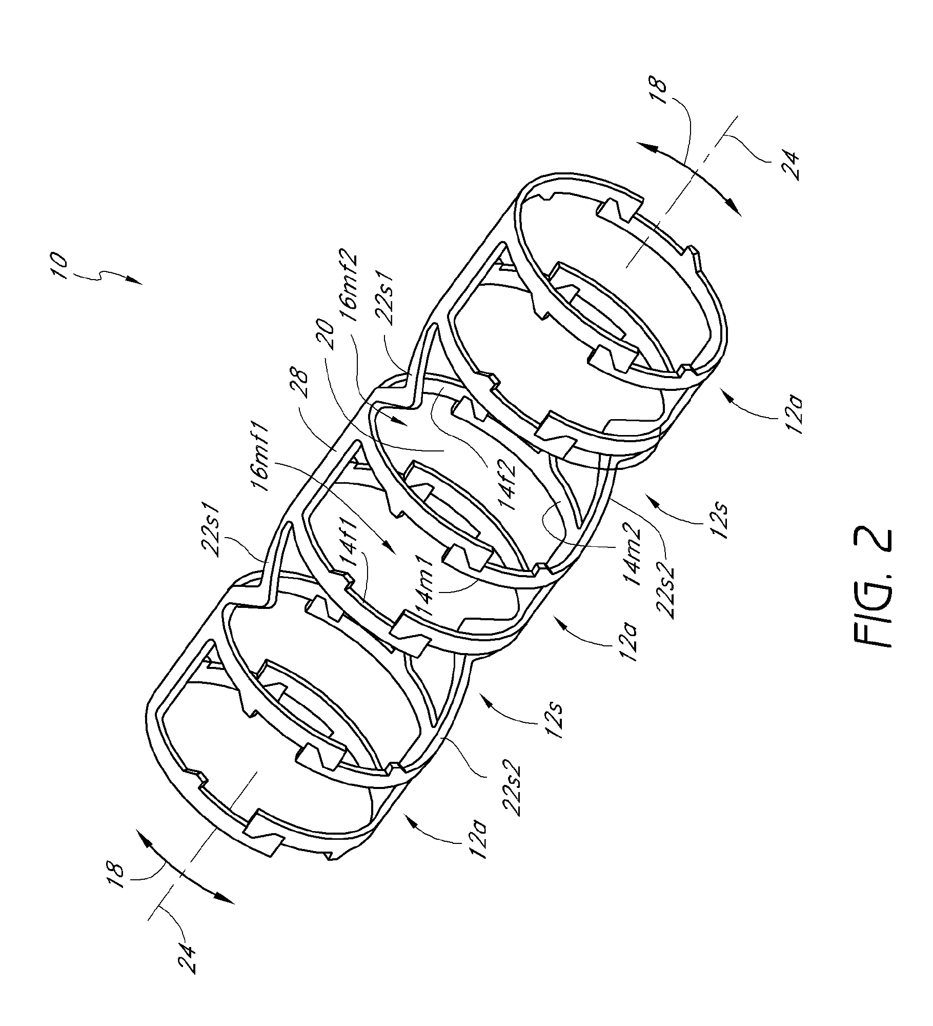
[0023]During manufacture and assembly of the axially nested embodiments, the device structural elements are substantially majorly or primarily positioned side by side (axially) in the predilated or non-expanded state to substantially reduce or minimize the device crossing profile and bulk in both the undeployed (non-expanded, predilated) and deployed (expanded, dilated) states. Advantageously, by substantially reducing or eliminating the excess bulk typically encountered with a radially nesting device design, embodiments of the inventions can be used to achieve competitive devices and crossing profiles with a wide variety of materials at a wide variety of thicknesses, thereby desirably allowing for optimum device design and performance.
[0024]Many conventional slide and lock vascular devices comprise elements that overlap each other in the radial direction, i.e., lay upon each other. This feature can limit that thickness of material that can be employed as well as the number of elements that can be employed. As the thickness or element number increases, competitive features of the device may be compromised, such as crossing profile. To provide acceptable crossing profiles, the thicknesses and the number of elements employed in these radially nesting devices is often reduced, which can have an impact on such features as reliability and device radial strength.
[0030]Some embodiments provide a slide-and-lock stent that comprises a tubular member. The tubular member is expandable from a first diameter to a second diameter. The tubular member comprises a first circumferential section and a second circumferential section. The circumferential sections are longitudinally arranged. A linkage section connects the circumferential sections and is configured to provide flexibility. Each of the circumferential sections comprises a first slide-and-lock element and a second slide-and-lock element. The corresponding slide-and-lock elements of each circumferential section are radially connected by a slidable articulating mechanism. Each of the first slide-and-lock elements comprises at least one tooth and each of the second slide-and-lock elements comprises at least one radially extending tooth. During expansion the teeth of the first slide-and-lock elements engage corresponding radially extending teeth of the second slide and lock sections. The teeth are configured to permit one-way sliding between the corresponding first and second slide-and-lock elements such that at least a portion of the corresponding first and second slide-and-lock elements is radially deflected during expansion from the first diameter to the second diameter.
[0031]Some embodiments provide a slide-and-lock stent that comprises a tubular member. The tubular member is expandable from a collapsed state to an expanded state and comprises a lumen. The tubular member comprises at least one slide-and-lock section. The slide-and-lock section comprises at least one first structural element and at least one second structural element that are radially interlocked with an articulating mechanism such as to provide circumferential relative motion between the first structural element and the second structural element. The articulating mechanism is configured to permit one-way sliding between the first structural element and the second structural element such that at least a portion of the first structural element and / or at least a portion of the second structural element is elastically deflected during expansion from the collapsed state to the expanded state. Advantageously, the radial interlocking between the structural elements substantially eliminates radial overlap and allows for a substantially clear through-lumen such that substantially no structure protrudes into the lumen in either the collapsed or the expanded state.
[0034]Embodiments of the inventions provide an improved stent: one that desirably is small enough and flexible enough when collapsed to permit uncomplicated delivery to the affected area; one that is sufficiently flexible upon deployment to conform to the shape of the affected body lumen; one that expands uniformly to a desired diameter, without change in length; one that maintains the expanded size, without significant recoil; one that has sufficient scaffolding to provide a clear through-lumen; one that supports endothelialization or covering of the stent with vessel lining, which in turn minimizes the risk of thrombosis; and one that has a greater capacity to deliver therapeutic agents to minimize injury, treat restenosis and other vascular diseases.
[0041]One key design aspect of embodiments of a slide and lock vascular device is its deployment ratio, that is, the ratio of final maximum diameter to initial compacted diameter. Depending upon the particular design being pursued or the application being addressed, the deployment ratio may vary. Advantageously, the stent of embodiments of the inventions allows the number of elements to be increased or decreased, that is, varied, as needed or desired, to achieve optimization of the deployment ratio as well as device performance, crossing profile, flexibility, among others. This desirably adds to the device versatility and utility.

Problems solved by technology

However, the dilation of the occlusion can cause fissuring of atherosclerotic plaque and damage to the endothelium and underlying smooth muscle cell layer, potentially leading to immediate problems from flap formation or perforations in the vessel wall, as well as long-term problems with restenosis of the dilated vessel.
Another problem inherent in many prior art stent configurations is the longitudinal contraction that such structures typically undergo as they are radially expanded.
This not only reduces the effective length of the stent in its deployed state but may cause abrasion trauma to be inflicted on the vessel walls during expansion.
The use of wire has a number of disadvantages associated therewith including for example, its substantially constant cross-section which may cause greater or lesser than an ideal amount of material to be concentrated at certain locations along the stent.
Additionally, wire has limitations with respect to the shapes it can be formed into thus limiting the expansion ratio, coverage area, flexibility and strength that can ultimately be attained therewith.
Unfortunately, the circumferential elements have free ends, protruding from the paired slots.
Both the free ends and the stand off may pose significant risks of thrombosis and / or restenosis.
Moreover, this stent design would tend to be rather inflexible as a result of the plurality of longitudinal backbones.
The disadvantage of these designs is that they tend to exhibit very poor longitudinal flexibility.
However, these coupled rolls lack vessel support between adjacent rolls.
Furthermore, these designs exhibit extensive overlapping of stent elements in multiple layers, which makes the delivery profile rather thick.
Although balloon expandable stents are the first stent type to be widely used in clinical applications, it is well recognized that balloon expandable stents have a variety of shortcomings which may limit their effectiveness in many important applications.
This is disadvantageous because it has been found that over-inflation may damage the blood vessel.
Furthermore, a deployed balloon expandable stent may exhibit chronic recoil over time, thereby reducing the patency of the lumen.
Still further, balloon expandable stents often exhibit foreshortening (i.e., a reduction in length) during expansion, thereby creating undesirable stresses along the vessel wall and making stent placement less precise.
Still further, many balloon expandable stents, such as the original Palmaz-Schatz stent and later variations, are configured with an expandable mesh having relatively jagged terminal prongs, which increases the risk of injury to the vessel, thrombosis and / or restenosis.
However, this type of stent utilizes the application of heat to produce expansion of the stent structure.
However, heat expandable stents have not gained widespread popularity due to the complexity of the devices, unreliable expansion properties and difficulties in maintaining the stent in its expanded state.
Still further, it has been found that the application of heat during stent deployment may damage the blood vessel.
In summary, although a wide variety of stents have been proposed over the years for maintaining the patency of a body lumen, none of the existing schemes has been capable of overcoming most or all of the above described shortcomings.
As the thickness or element number increases, competitive features of the device may be compromised, such as crossing profile.
Thus, as the interconnection member passes through the engagement aperture during expansion, the movement of the interconnection member relative to the engagement aperture can be limited by the stop member.

Method used


Image

  • Axially nested slide and lock expandable device
  • Axially nested slide and lock expandable device
  • Axially nested slide and lock expandable device

Examples


Embodiment Construction

[0124]While the description sets forth various embodiment specific details, it will be appreciated that the description is illustrative only and should not be construed in any way as limiting the inventions. Furthermore, various applications of the inventions, and modifications thereto, which may occur to those who are skilled in the art, are also encompassed by the general concepts described herein.

[0125]The term “stent” is used herein to designate embodiments for placement in (1) vascular body lumens (i.e., arteries and / or veins) such as coronary vessels, neurovascular vessels and peripheral vessels for instance renal, iliac, femoral, popliteal, subclavian and carotid; and in (2) nonvascular body lumens such as those treated currently i.e., digestive lumens (e.g., gastrointestinal, duodenum and esophagus, biliary ducts), respiratory lumens (e.g., tracheal and bronchial), and urinary lumens (e.g., urethra); (3) additionally such embodiments may be useful in lumens of other body sys...


PUM

PropertyMeasurementUnit
Lengthaaaaaaaaaa
Flexibilityaaaaaaaaaa

Abstract

The inventions relate generally to expandable medical implants for maintaining support of a body lumen and, in particular, to an axially nested, diametrically expandable, slide and lock vascular device for enlarging an occluded portion of a vessel. The axially nested vascular device desirably achieves both competitive crossing profiles while maintaining other key features, such as, for example, radial strength and luminal patency. The collapsed profile can also be made very thin without compromising radial strength. Thus, the vascular device can advantageously be deployed in small and difficult to reach areas or vessels. The axial nesting substantially eliminates radial overlap between mating structural elements thereby desirably allowing for a low, uniform profile.

Description

CROSS-REFERENCE TO RELATED APPLICATIONS[0001]This application is a continuation-in-part of U.S. application Ser. No. 11 / 196,800, filed Aug. 2, 2005, the entirety of which is hereby incorporated herein by reference.BACKGROUND OF THE INVENTIONS[0002]1. Field of the Inventions[0003]The inventions relate generally to expandable medical implants for maintaining support of a body lumen. More particularly, the inventions relate to a predominantly axially nested, diametrically expandable, slide and lock device for enlarging a portion of a body lumen.[0004]2. Description of the Related Art[0005]Stents or expandable stent grafts are implanted in a variety of body lumens in an effort to maintain their patency. The body lumens no matter how large or small may be vascular and nonvascular. These devices are typically intraluminally implanted by use of a catheter, which is inserted at an easily accessible location and then advanced to the deployment site. The stent is initially in a radially compr...

Claims


Application Information

Patent Timeline
IPC IPC(8): A61F2/06A61F2/92
CPCA61F2/91A61F2/915A61F2250/0067A61F2002/91591A61F2210/0004A61F2/92A61F2/93A61F2/94A61F2210/0014A61F2220/0025A61F2250/001A61F2250/0098
Inventor MORRIS, ANDREWSCHMID, ERICSHERIFF, JEFFREYFELKINS, BRANDON
Owner REVA MEDICAL
Learn More