Interface apparatus, main apparatus and control method for use in the interface apparatus

a technology of interface apparatus and main apparatus, which is applied in the direction of digital transmission, data switching network, instruments, etc., can solve the problems of failure of sip network or registration server, failure to achieve countermeasures,

Inactive Publication Date: 2009-01-29
KK TOSHIBA
View PDF4 Cites 10 Cited by
  • Summary
  • Abstract
  • Description
  • Claims
  • Application Information

AI Technical Summary

Problems solved by technology

Meanwhile, in the system, it is fully supposed that a failure occurs in the SIP network or the registration server.
However, the aforementioned method takes the countermeasures only to cope with the case of the occurrence of the failure in the registration server, countermeasures to cope with other occurrences of failures has been in examination stage, and the method has not attained the countermeasures yet.

Method used


Image

  • Interface apparatus, main apparatus and control method for use in the interface apparatus
  • Interface apparatus, main apparatus and control method for use in the interface apparatus
  • Interface apparatus, main apparatus and control method for use in the interface apparatus

Examples


first embodiment

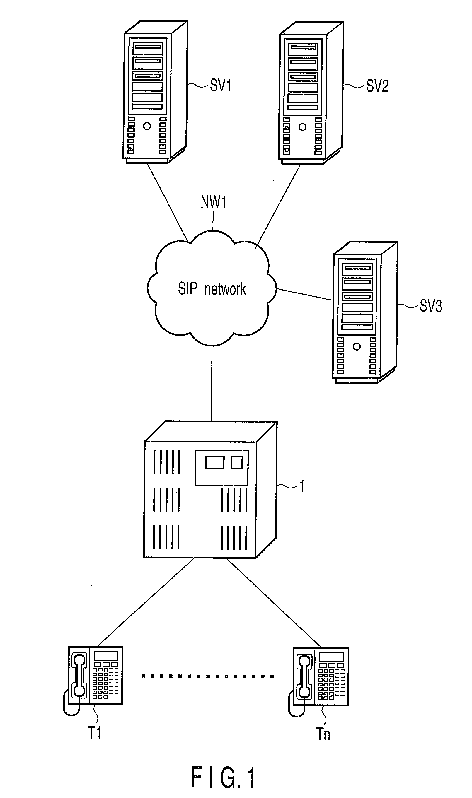
[0019]FIG. 1 shows a schematic configuration view of a telephone system of the first embodiment regarding the invention, and a reference FIG. 1 designates a main apparatus.

[0020]The main apparatus 1 houses a plurality of key telephone terminals T1-Tn (n is a natural number). SIP servers SV1-SV3 are connected to the main apparatus 1 via an SIP network NW1.

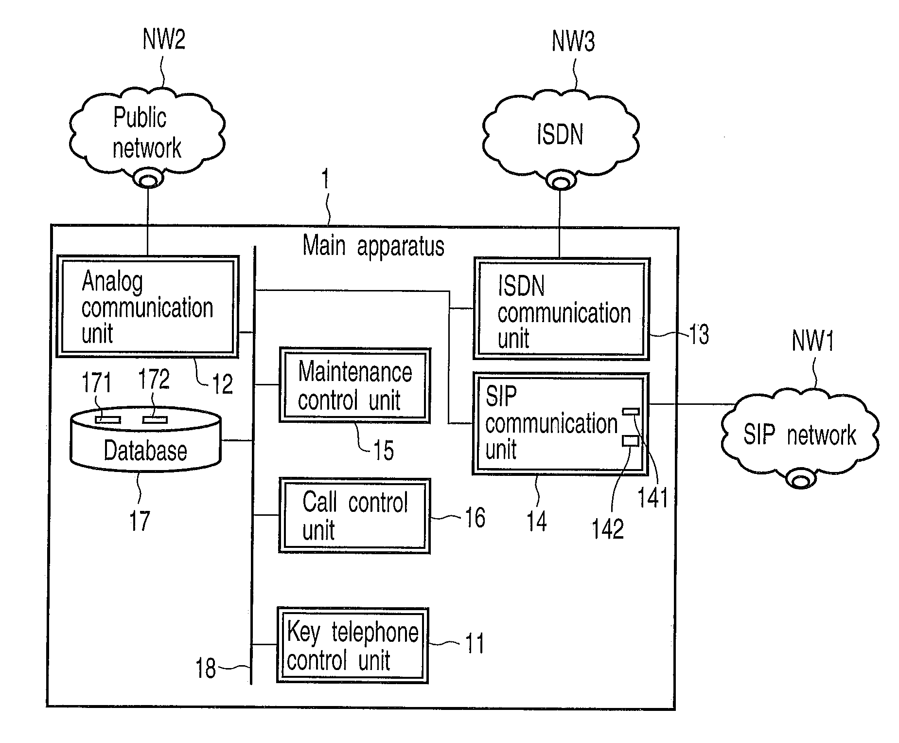
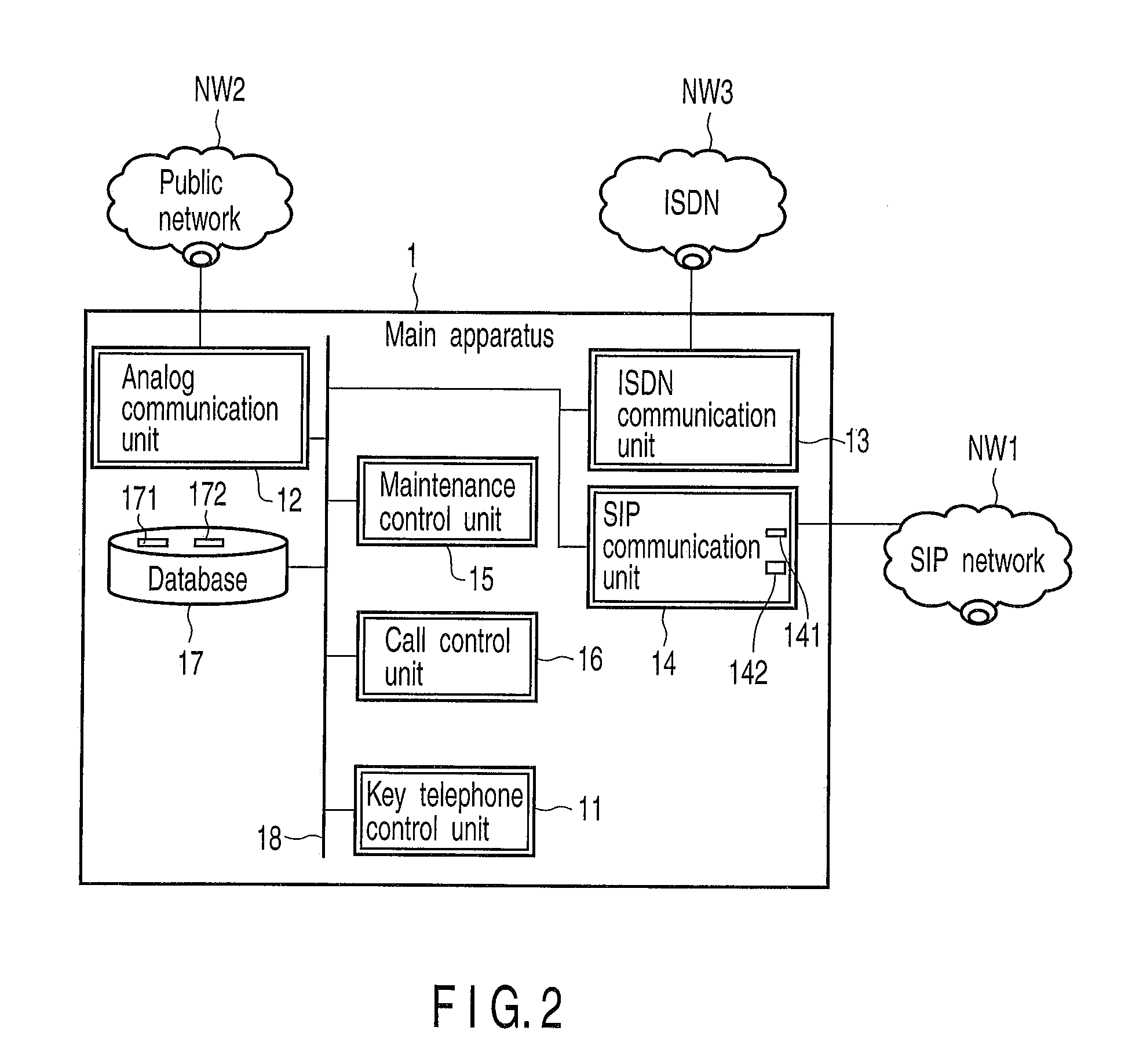
[0021]FIG. 2 shows a functional block diagram of the main apparatus 1.

[0022]The main apparatus 1 includes a key telephone control unit 11, an analog communication unit 12, an ISDN communication unit 13, an SIP communication unit 14, a maintenance control unit 15, a call control unit 16 and a database 17. These key telephone control unit 11, analog communication unit 12, ISDN communication unit 13, SIP communication unit 14, maintenance control unit 15, call control unit 16 and database 17 are mutually connected through a control bus 18. The database 17 includes an SIPURI table 171 and a low cost route (LCR) table 172.

[0023]A plurali...

second embodiment

[0051]FIG. 7 shows a block diagram for explaining LCR originating operations of the second embodiment regarding the invention and FIG. 8 shows a sequence view illustrating transmission and reception operations of signals among a maintenance control unit 15, a SIP communication unit 14 and SIP servers SV1-SV3 in LCR origination.

[0052]In FIG. 7, it is assumed that LCR originating operations are performed by a key telephone terminal T1 housed in a main apparatus 1. Then, in the main apparatus 1, a call control unit 16 obtains all trunks capable of being grasped in accordance with the order of priority from an LCR table 172 based on dial information input from the key telephone terminal T1. As a result, if a first route is an SIP trunk, the call control unit 16 transmits an ‘originating connection message’ to the SIP communication unit 14.

[0053]The SIP communication unit 14 transmits an ‘INVITE message’ to the SIP server SV1; however if any response cannot be received from the SIP serve...


PUM


Abstract

According to one embodiment, an interface apparatus includes a register which registers each connection ID of the plurality of communication terminals registered in a registration table of the main apparatus in a registration server on the SIP network at a predetermined registration cycle, a connector which connects among the plurality of communication terminals and the SIP network, to make communication among the plurality of communication terminals registered by the resister and the SIP network, a detector which detects a failure regarding the communication in a state where communication is made with the registration server, and a controller which makes communication with the registration server at a recovery cycle that is shorter than the registration cycle, to recover connection to the registration server, when the failure is detected.

Description

CROSS-REFERENCE TO RELATED APPLICATIONS[0001]This application is based upon and claims the benefit of priority from Japanese Patent Application No. 2007-194830, filed Jul. 26, 2007, the entire contents of which are incorporated herein by reference.BACKGROUND[0002]1. Field[0003]One embodiment of the present invention relate to an interface apparatus to connect between a plurality of communication terminals each having communication functions defined by a Session Initiation Protocol (SIP), and relates to a main apparatus to house the interface apparatus therein and a control method for use in the interface apparatus.[0004]2. Description of the Related Art[0005]In recent years, an Internet Protocol (IP) telephone system which transmits and receives bi-directionally in real time images and voice as packet data has become widespread. The IP telephone system can perform extension communication and outside-line origination and termination among main apparatuses via the IP network as well a...

Claims


Application Information

Patent Timeline
Patent Type & Authority Applications(United States)
IPC IPC(8): G06F15/173H04L12/70H04M3/00H04Q3/58
CPCH04L69/40H04L65/1006H04L65/1104
Inventor NAKAI, HIDEAKI
Owner KK TOSHIBA
Why Eureka
Try Eureka