

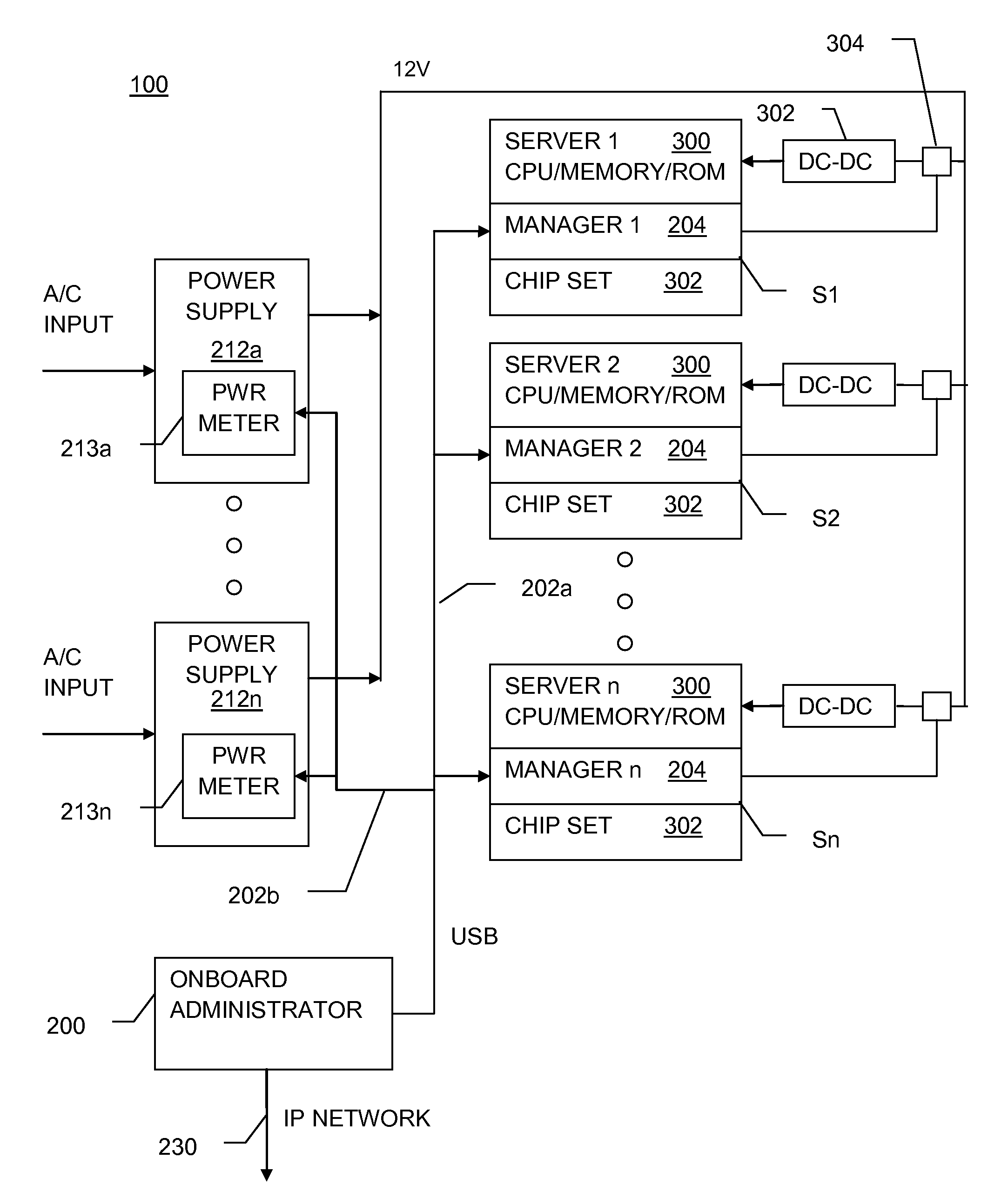
Centralized server rack management using USB
a server rack and server technology, applied in the field of computer systems, can solve problems such as cable clutter in the racks
- Summary
- Abstract
- Description
- Claims
- Application Information
AI Technical Summary
Benefits of technology
Problems solved by technology
Method used
Image

Examples
Embodiment Construction
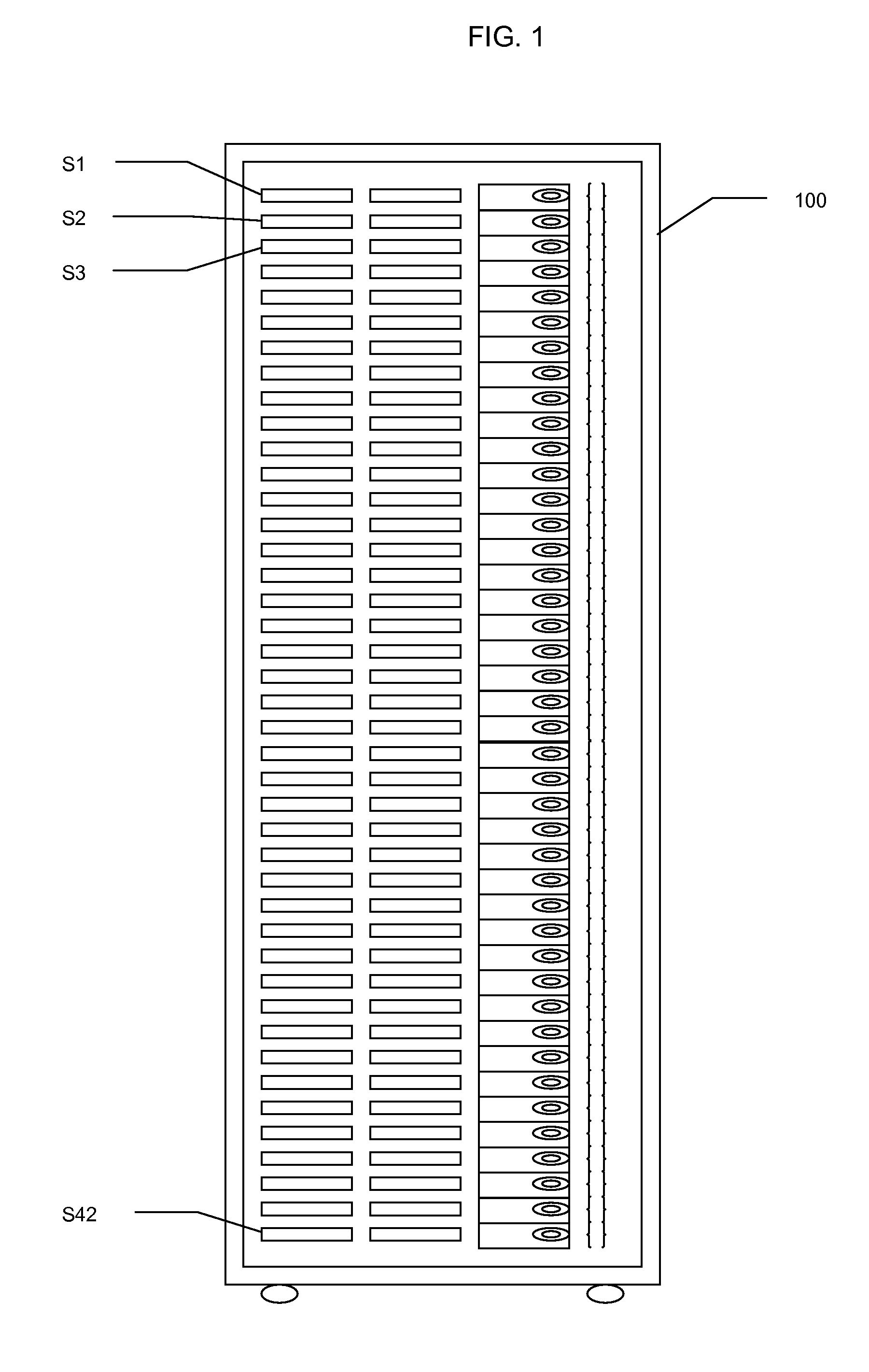
[0015]FIG. 1 illustrates a 42 U rack system 100 containing 42 servers S1-S42. Newer servers are even thinner, some being referred to as “pizza boxes” and being only 1 U. With these servers, a single rack may hold up to 42 servers. Another embodiment of a rack system using blade servers is referred to as a blade server.
[0016]In a standard server-rack configuration, 1 U (one rack unit, 19″ wide and 1.75″ tall) is the minimum possible size of any equipment. The principal benefit of blade computing is that components are no longer restricted to these minimum size requirements. The most common computer rack form-factor being 42 U high, this limits the number of discrete computer devices directly mounted in a rack to 42 components. Blades do not have this limitation; densities of 100 computers per rack and more are achievable with the current generation of blade systems.
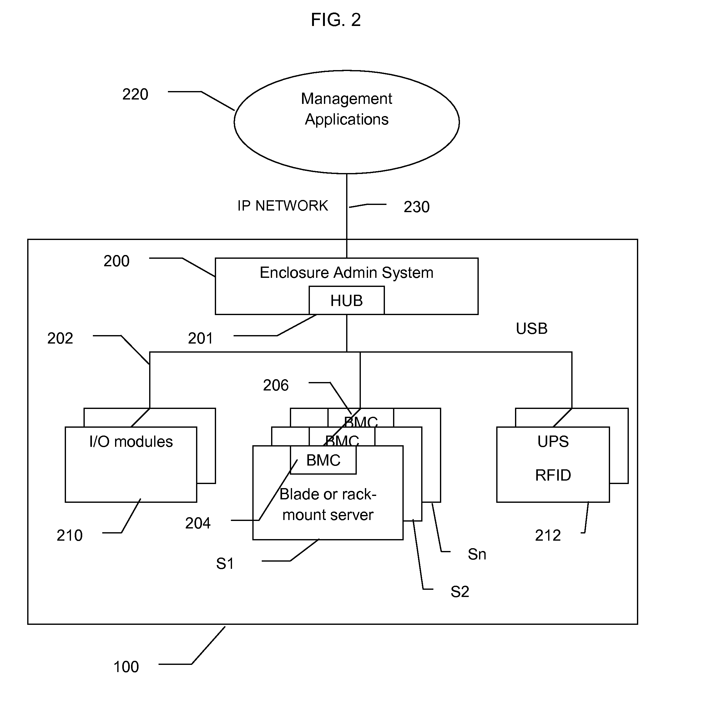
[0017]An enterprise IT (information technology) administrator individually manages rackmount servers in data center or r...
PUM
 Abstract
Description
Claims
Application Information