Broadcast receiving apparatus and pay program providing system

a technology of which is applied in the field of broadcast receiving apparatus and pay program providing system, can solve the problems of play it back later, inability to collect the viewing fee almost unfailingly, and inability to record the pay program

Inactive Publication Date: 2009-01-29
SHARP KK
View PDF9 Cites 93 Cited by
  • Summary
  • Abstract
  • Description
  • Claims
  • Application Information

AI Technical Summary

Benefits of technology

[0008]In view of the conventionally experienced problems described above, an object of the present invention is to provide broadcast receiving apparatuses and pay program providing systems that, without hampering collection of a viewing fee, make it easy for a viewer to record a pay program without the need for making a subscription agreement or the like in advance.

Problems solved by technology

The above-described conventional method makes it possible to collect the viewing fee almost unfailingly, because the party from which the viewing fee should be collected is known by the contents of the subscription agreement.
However, this method is often inconvenient in particular for the viewer, because it is based on the assumption that the viewer makes a subscription agreement with the program provider in advance.
As a result, the following problems arise.
If the pay program will be broadcast soon (for example, 10 minutes later), the viewer fails to make a subscription agreement about the pay program in time, and therefore cannot record the pay program and play it back later.
On the other hand, however, if the viewer is allowed to record any pay program and play it back without any inhibition, the pay program provider may find it difficult to collect the viewing fee.

Method used


Image

  • Broadcast receiving apparatus and pay program providing system
  • Broadcast receiving apparatus and pay program providing system
  • Broadcast receiving apparatus and pay program providing system

Examples


example 1

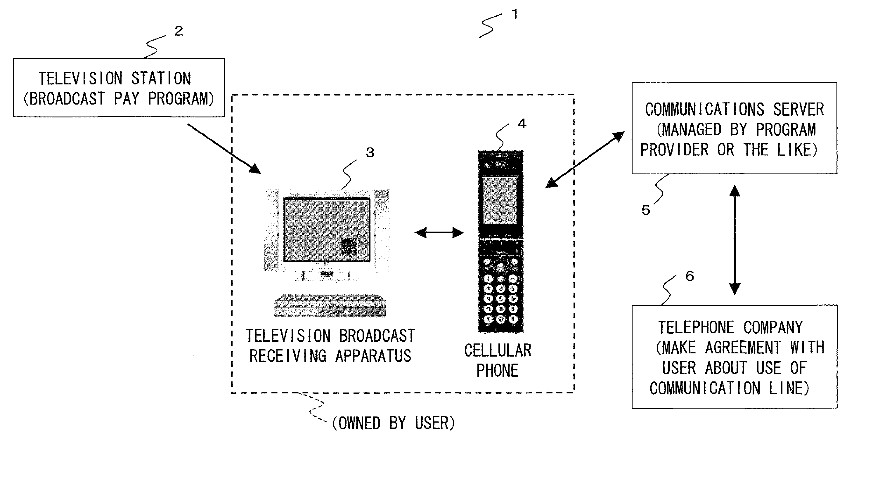
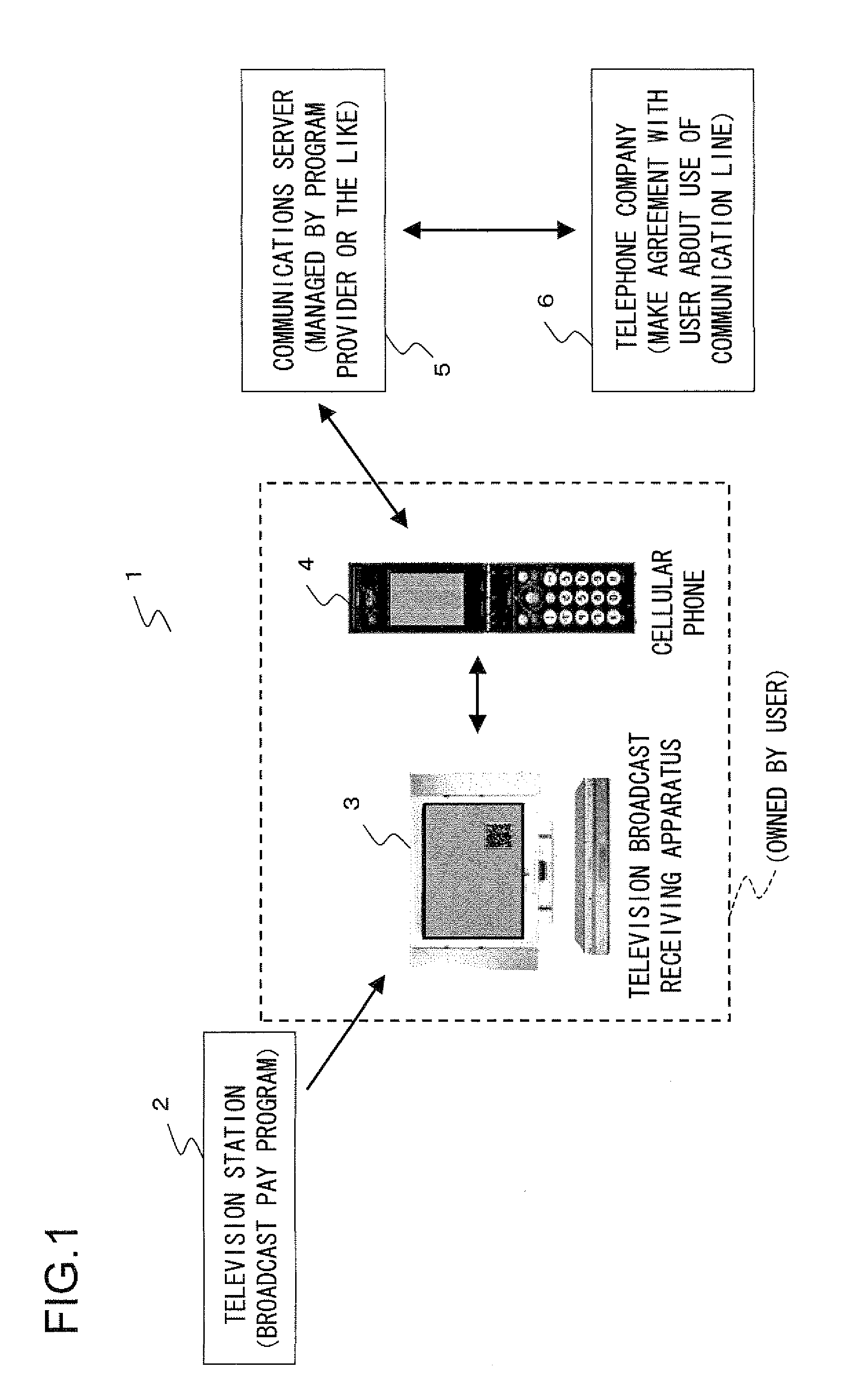
[0059]Example 1 of the present invention will be described, taking up as an example a pay program providing system. An outline of the configuration of this pay program providing system is shown in FIG. 1. As shown in this figure, a pay program providing system 1 includes a television station 2, a television broadcast receiving apparatus 3, a cellular phone 4, a communications server 5, and a telephone company 6. Here, assume that the television broadcast receiving apparatus 3 and the cellular phone 4 belong to the user.

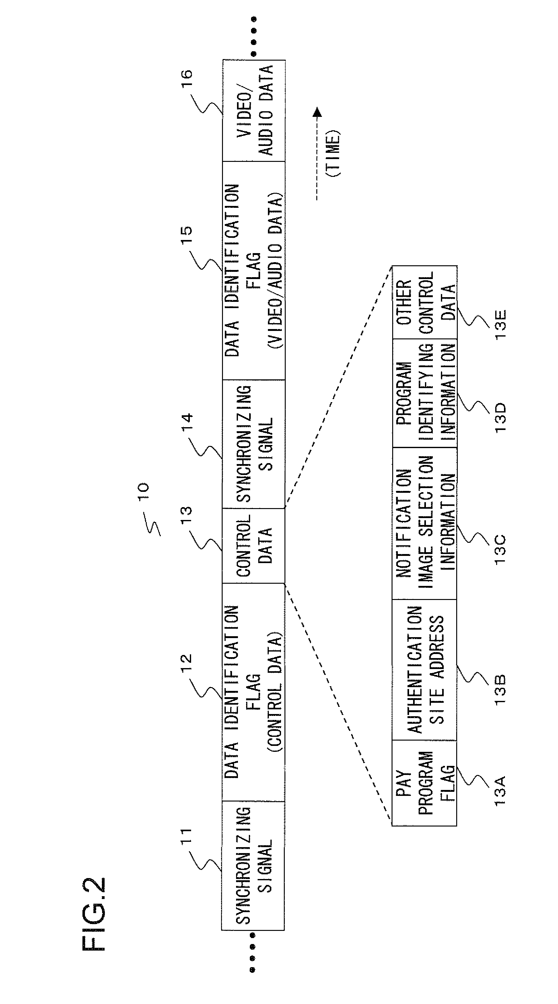
[0060]First, the television station 2 will be described. The television station 2 broadcasts information (such as video data) related to the contents of a program produced by a program provider as a data stream by using an RF signal, for example. Here, with reference to FIG. 2, the data structure of the data stream will be explained.

[0061]As shown in FIG. 2, a data stream 10 consists of a synchronizing signal 11, a data identification flag 12, control data 13, a synch...

example 2

[0115]Next, Example 2 of the invention will be described. This example differs from Example 1 only in the contents of stream data transmitted from the television station 2 and matters concerning a display of the pay program guide image in the receiving apparatus 3. In other respects, the configuration of Example 2 is basically the same as that of Example 1, and overlapping explanations will be omitted.

[0116]The contents of stream data of this example is shown in FIG. 14. The stream data 10 of this example differs from that of Example 1 in that pay program guide display data 13F is inserted in place of the notification image selection information 13C. This pay program guide display data 13F corresponds to data for displaying a pay program guide image of Example 1.

[0117]That is, in Example 1, the receiving apparatus 3 previously stores a plurality of data for a notification image (a portion of a pay program guide image outside the QR code 17), and displays one of them according to the...

example 3

[0119]Next, Example 3 of the invention will be described. This example differs from Example 1 only in that key information is encrypted. In other respects, the configuration of this example is basically the same as that of Example 1, and overlapping explanations will be omitted.

[0120]In this example, key information transmitted from the cellular phone 4 to the receiving apparatus 3 by using infrared communication is encrypted by a public key encryption-based encryption scheme. It is to be noted that public key encryption is an encryption scheme in which a public key and a private key are used in a pair, and to decrypt the information encrypted with a public key requires a corresponding private key. An example of the public key encryption is an RSA scheme using the difficulties of factorization into prime factors.

[0121]Hereinafter, with reference to a flow chart shown in FIG. 15, the procedures of this example will be described. First, the program provider produces a public key (here...


PUM


Abstract

A broadcast receiving apparatus receives a broadcast signal containing video image information representing a video image, pay program identifying information indicating whether or not the video image is a pay program video image, and address information indicating a predetermined communications server, the broadcast signal containing the video image information, the pay program identifying information, and the address information in a predetermined format. The broadcast receiving apparatus has: a display portion displaying the video image; a pay program judging portion judging whether or not the video image information is pay program video image information based on the pay program identifying information; and a recording portion recording the video image information. If the pay program judging portion judges that the video image information is pay program video image information, the recording portion records the address information in addition to the video image information. A pay program providing system includes the broadcast receiving apparatus. Thus, provided are the broadcast receiving apparatus and the pay program providing system that, without hampering collection of a viewing fee, make it easy for a viewer to record a pay program without the need for making a subscription agreement or the like in advance.

Description

[0001]This nonprovisional application claims priority under 35 U.S.C. § 119(a) on Patent Application No. 2007-194476 filed in Japan on Jul. 26, 2007, the entire contents of which are hereby incorporated by reference.BACKGROUND OF THE INVENTION[0002]1. Field of the Invention[0003]The present invention relates to broadcast receiving apparatuses that receive broadcast signals, and to provide pay program providing systems using such broadcast receiving apparatuses.[0004]2. Description of Related Art[0005]Currently, a fee-based service whereby a broadcast program is provided for a fee (pay program providing service) is available. Such a service is generally based on the assumption that a viewer makes a subscription agreement with a program provider in advance, such that, for example, the program provider ensures collection of a viewing fee. For example, a pay program is not allowed to be watched and recorded until the viewer makes a subscription agreement with the program provider. Depen...

Claims


Application Information

Patent Timeline
Patent Type & Authority Applications(United States)
IPC IPC(8): H04N7/173G06K19/06H04N5/765H04N5/91H04N21/235H04N21/2543H04N21/266H04N21/433H04N21/4623H04N21/6334H04N21/6377H04N21/858
CPCG06Q20/145G06Q20/32G06Q20/3276G07F17/16H04N21/47211H04N21/2543H04N21/4147H04N21/4334H04N7/17318
Inventor HOGYOKU, ITARU
Owner SHARP KK
Why Eureka
Try Eureka