Eureka AIR delivers breakthrough ideas for toughest innovation challenges, trusted by R&D personnel around the world.

Hydraulic circuit for rapid bucket shake out

Inactive Publication Date: 2009-02-05
CATERPILLAR INC
View PDF12 Cites 19 Cited by
  • Summary
  • Abstract
  • Description
  • Claims
  • Application Information

AI Technical Summary

Benefits of technology

[0007]A hydraulic circuit is disclosed. The hydraulic circuit may have a variable displacement pump configured to create a flow of pressurized fluid. The variable displacement pump may have a fluidic displacement control configured to vary the flow of pressurized fluid based on a first fluid signal, and an electronic displacement control configured to vary the flow of pressurized fluid based on an electronic signal. The flow of pressurized fluid may be controlled by the one of the fluidic displacement control and the electronic displacement control that is requesting the smallest flow of pressurized fluid. The hydraulic circuit may also have a first control valve connected between an outlet of the pump and an input of the fluidic displacement control, and the first control valve may be configured to transmit the first fluid signal to the input of the fluidic displacement control. The hydraulic circuit may further have a controller operable in a shake out mode. The shake out mode may include directing pressurized fluid from the pump outlet to the input of the fluidic displacement control to cause the fluidic control to request a maximum flow of pressurized fluid, and transmitting the electronic signal to the electronic displacement control to cause the electronic displacement control to vary the flow of pressurized fluid.

Problems solved by technology

A problem associated with type of pump is that it can respond slowly to demand.
This delay ill transition to full flow and subsequent rapid return to a low flow condition may cause problems when an actuator or implement must be moved rapidly back and forth, such as when an operator needs to shake a bucket.
In such a situation, the pump may have difficulty responding quickly to demands to rapidly extend, stop, and then retract the bucket actuator.
Although the system disclosed in the '809 patent may allow a rapid initial extension of a bucket actuator, such as during a bucket shaking operation, it may have limited applicability.
This disabling may result in an inefficient system, because any excess fluid must be dumped directly to a tank, and the power used to pressurize the fluid is wasted.
Additionally, the pressurized fluid being dumped across a relief valve to the tank may result in an undesired heating of the fluid, which may require a fluid cooling system, and / or prematurely degrade the quality and effectiveness of the fluid.

Method used


Image

  • Hydraulic circuit for rapid bucket shake out
  • Hydraulic circuit for rapid bucket shake out
  • Hydraulic circuit for rapid bucket shake out

Examples


Embodiment Construction

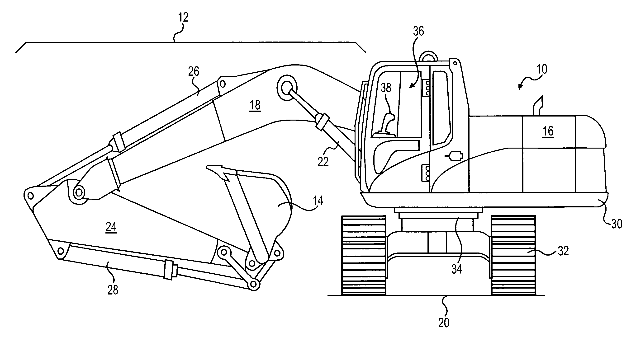
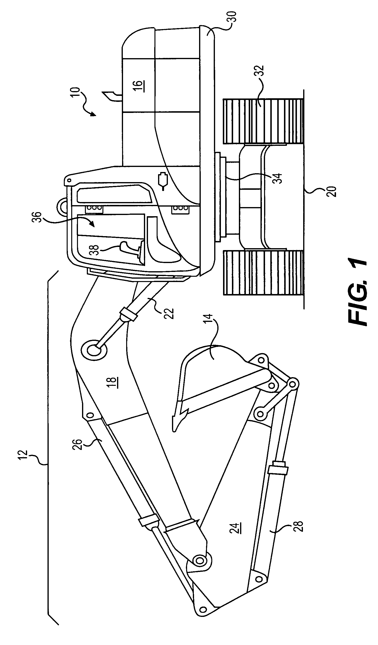
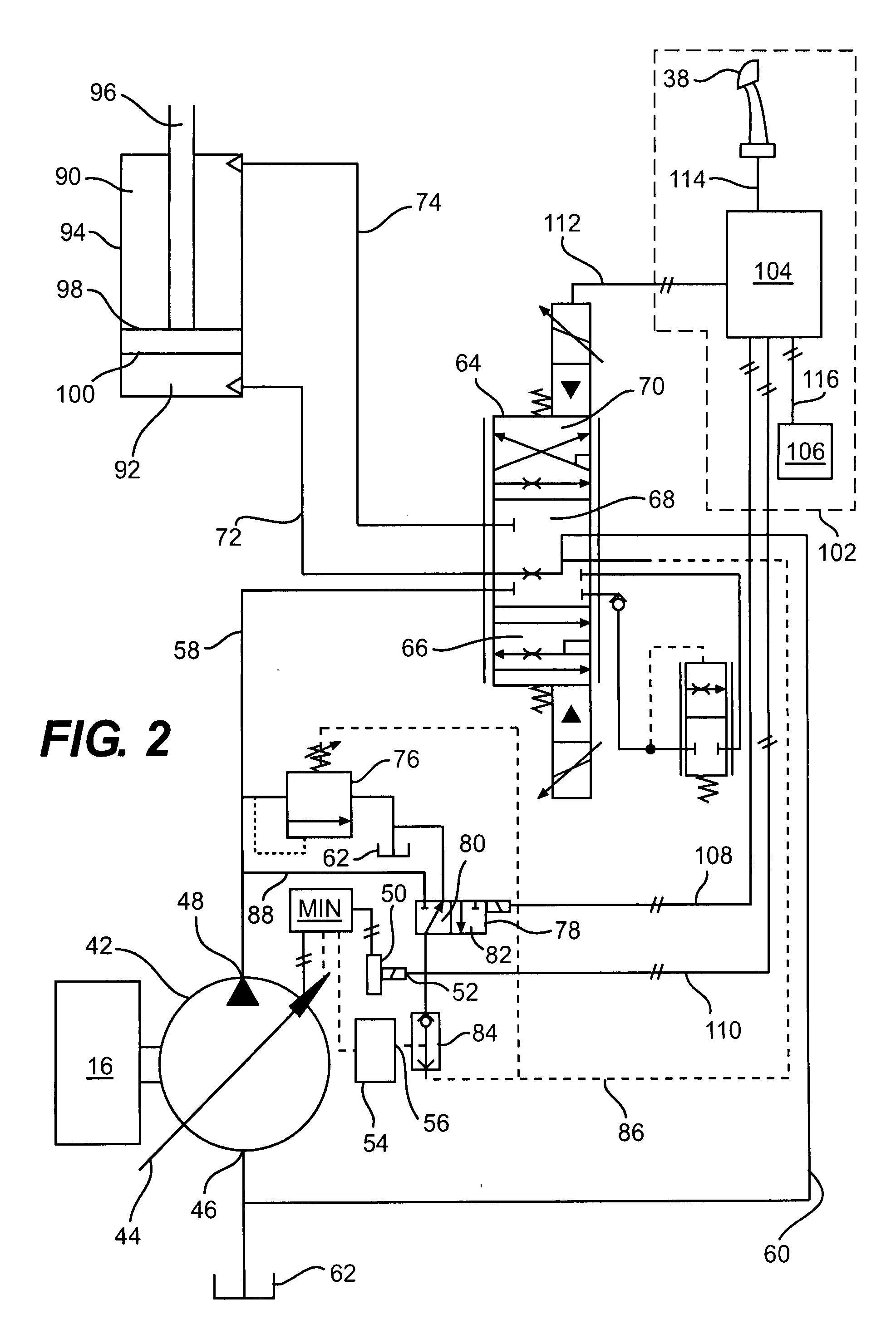
[0011]FIG. 1 illustrates an exemplary machine 10 having multiple systems and components that cooperate to accomplish a task. Machine 10 may embody a fixed or mobile machine that performs some type of operation associated with an industry such as mining, construction, farming, transportation, or any other industry known in the art. For example, machine 10 may be an earth moving machine such as the excavator depicted in FIG. 1. Alternatively, machine 10 may be a dozer, a loader, a backhoe, a motor grader, a haul truck, or any other earth-moving or task-performing machine. Machine 10 may include an implement system 12 configured to move a work tool 14, a power source 16 that drives implement system 12, and an operator station 36 for operator control of machine 10 and implement system 12.

[0012]Implement system 12 may include a linkage structure moved by fluid actuators to position and operate work tool 14. Specifically, implement system 12 may include a boom member 18 that is vertically...


PUM


Abstract

A hydraulic circuit is disclosed. The hydraulic circuit may have a variable displacement pump. The variable displacement pump may have a fluidic displacement control configured to vary a flow of pressurized fluid based on a fluid signal and an electronic displacement control configured to vary the flow of pressurized fluid based on an electronic signal. The flow of pressurized fluid may be controlled by the one of the fluidic and electronic displacement controls that requests the smallest flow of pressurized fluid. The hydraulic circuit may also have a control valve connected between the pump and the fluidic displacement control, and the control valve may be configured to transmit the fluid signal to the fluidic displacement control. The hydraulic circuit may further have a controller configured to transmit a fluid signal to cause the fluidic control to request a maximum flow of pressurized fluid, and transmit an electronic signal requesting a flow smaller than the maximum flow, which causes the electronic displacement control to vary the flow of pressurized fluid.

Description

TECHNICAL FIELD[0001]The present disclosure relates generally to a hydraulic circuit, and, more particularly, to a hydraulic circuit used to rapidly shake material out of a machine bucket.BACKGROUND[0002]Construction machines such as, for example, dozers, loaders, excavators, motor graders, and other types of heavy machinery use a hydraulic circuit to operate a variety of actuators and associated implements. During operation of the construction machines, there may occasionally arise a need for rapid operation of the actuators to move the implements back and forth (i.e. to shake the implement). For example, an implement such as a bucket is often used for excavating earthen materials, and due to the adhesive nature of the materials, an operator may need to shake the bucket to adequately remove material that is stuck to or remains within the bucket. An operator may also shake the bucket to break into hard ground. Such shaking can be manually accomplished by a rapid back and forth movem...

Claims


Application Information

Patent Timeline
IPC IPC(8): F15B11/10
CPCE02F9/2004F15B2211/7733E02F9/2228E02F9/2296F15B11/05F15B11/165F15B2211/20523F15B2211/20546F15B2211/30555F15B2211/3111F15B2211/327F15B2211/6336F15B2211/6346F15B2211/653F15B2211/7053E02F9/221
Inventor BRINKMAN, JASON L.KUEHN, JEFFREY L.
Owner CATERPILLAR INC
Why Eureka
Eureka Blog
Learn More