Variable displacement pump

a variable-discharge pump and pump body technology, applied in the direction of liquid fuel engines, machines/engines, rotary piston liquid engines, etc., can solve the problems of unfavorable or difficult to achieve the oil pressure required for the piston cooling oil jet, waste of oil quantity and driving power, etc., to achieve the effect of improving reliability and reducing energy consumption

Inactive Publication Date: 2015-01-22
HITACHI AUTOMOTIVE SYST LTD
View PDF10 Cites 25 Cited by
  • Summary
  • Abstract
  • Description
  • Claims
  • Application Information

AI Technical Summary

Benefits of technology

[0006]Therefore, it is an object of the present invention to provide a variable displacement pump adequate for various situations, and more specifically to provide a variable displacement pump adequate for reducing energy consumption by decreasing a discharge oil pressure in a normally used oil temperature state in a low and medium engine speed region and for improving reliability by increasing the discharge oil pressure in a higher oil temperature state, to enable the operation of the piston cooling oil jet.

Problems solved by technology

However, in the low and medium engine speed region, even if the engine oil temperature is increased, it is unfeasible or difficult to achieve an oil pressure required for the piston cooling oil jet.
If the oil pressure in the low and medium speed region is set at a relatively high level required for the oil jet, the oil may be injected from the oil jet at a normal oil temperature requiring no oil jet, resulting in useless consumption of the oil quantity and driving power.

Method used


Image

  • Variable displacement pump
  • Variable displacement pump
  • Variable displacement pump

Examples


first embodiment

Operation of First Embodiment

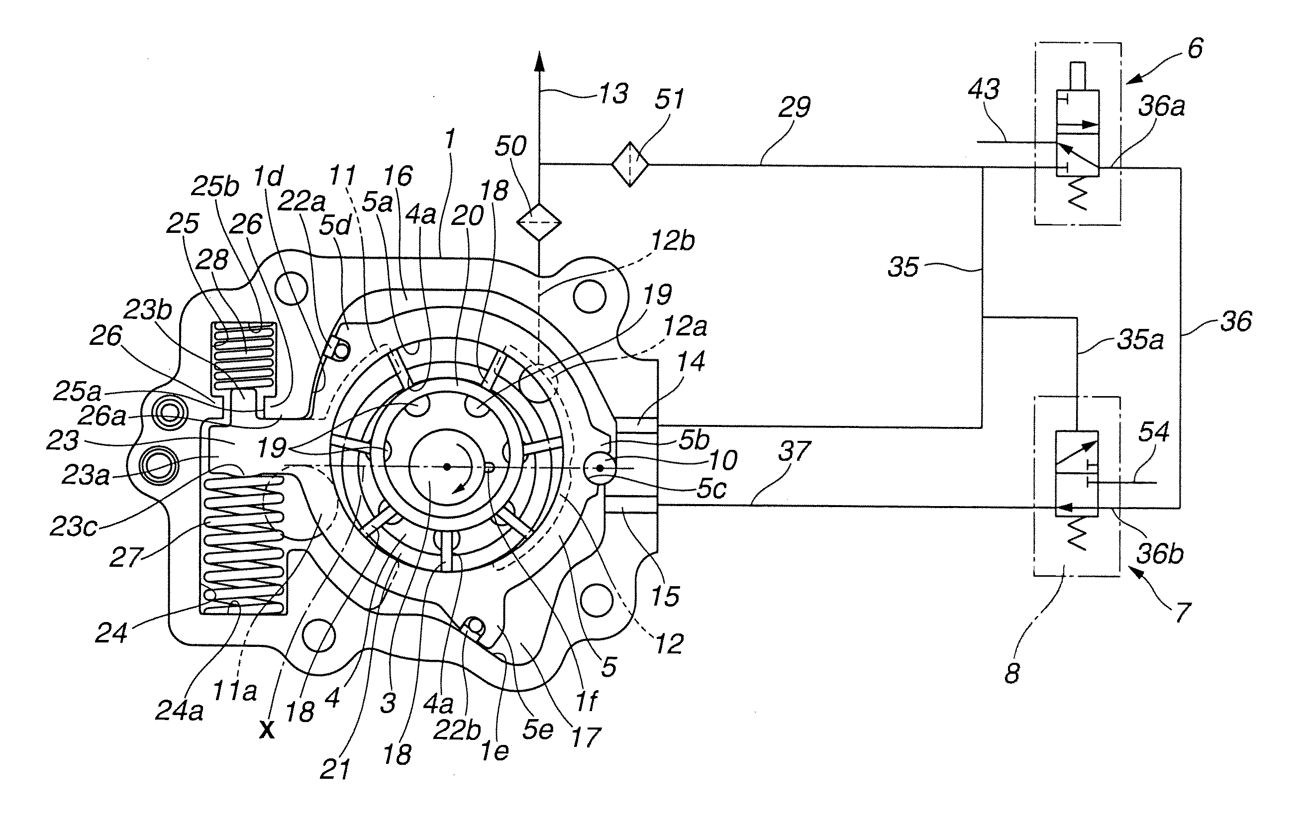
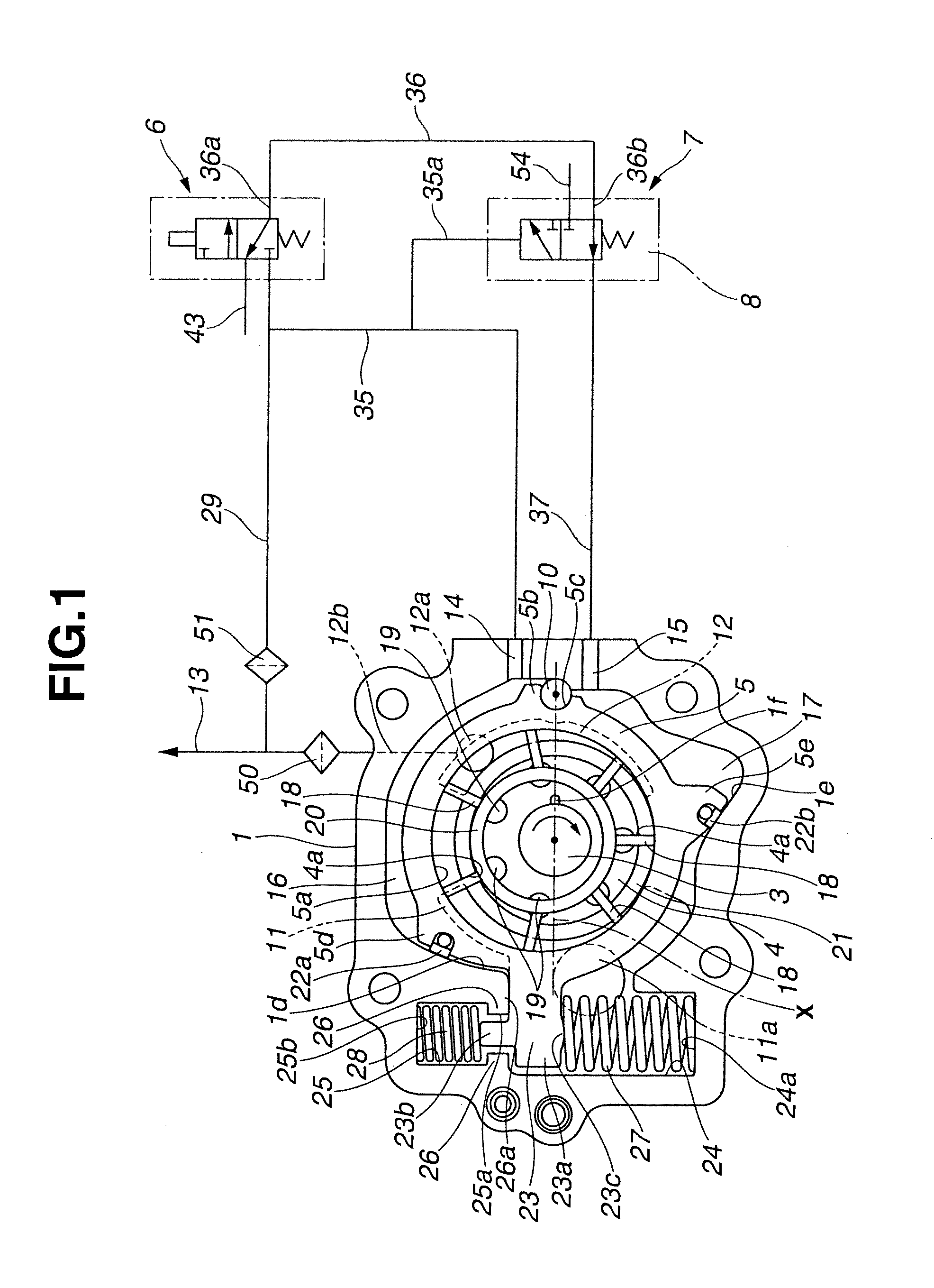
[0089]In the state shown in FIG. 1, by the resulting force of the spring forces of first coil spring 27 and second coil spring 28, the upper surface of arm 23 of cam ring 5 abuts against stopper surface 26a in a lower end of one retaining portion 26. In this state, the eccentricity is greatest, and the volume change of each pumping chamber 21 with rotation is greatest. Therefore, the discharge volume or capacity of the oil pump is greatest.

[0090]The rotor 4 of the pump main body is rotated in the clockwise direction as shown by an arrow in FIG. 1, by the drive shaft 3, and hence the pump chambers 21 expand in the state opening to the intake port 11 in a left side region on the left side in FIG. 1. Intake port 11 is allowed to suck the oil from the oil pan outside the pump through the intake hole or opening 11a. In a right side region in FIG. 1, the pump chambers 21 shrink in the state opening to the drain port 12, so that the oil is discharged to dischar...

second embodiment

[0114]FIG. 11 shows a variable displacement pump according to a second embodiment. The pilot valve 7 is connected with a downstream end of a branch passage 36c branching off from the connection passage 36. The downstream end of branch passage 36c is connected to the upper portion bounded by the pressure receiving surface 52e of first land 52a of spool 52. Thus, the spool 52 receives the discharge pressure on the downstream side of thermosensitive valve 6. With this arrangement, the variable displacement pump according to the second embodiment can provide operations and effects similar to those of the first embodiment.

third embodiment

[0115]FIGS. 12˜14 show a variable displacement pump according to a third embodiment. In the third embodiment, unlike the first embodiment, the pilot valve 7 is configured to have a drain function of second control chamber 17 in the initial state, instead of thermosensitive valve 6.

[0116]Specifically, in thermosensitive valve 6, as shown in FIGS. 13A and 13B, the drain port (43) is eliminated, and the cylinder bore 31 is formed with three openings: the open end 29a of branch passage 29, the open end 36a of connection passage 36, and the open end 35a of first communication passage 35. Moreover, the annular groove (32e) is not formed in the outside circumferential surface of valve member 32.

[0117]In the pilot valve 7, as shown in FIGS. 14A-14C, the open end of branch passage 36c of connection passage 36 is opened into the upper portion bounded by the pressure receiving surface 52e of first land 52a of spool 52; and an open end 56a of a second drain port 56 is opened to a slide bore 50 ...


PUM


Abstract

A variable displacement pump includes an urging mechanism to urge a cam ring in an eccentric direction and to increase the urging force when an eccentricity is decreased, a first control chamber to apply a force to the cam ring in a direction decreasing the eccentricity, and a second control chamber to apply a force, to the cam ring, in a direction increasing the eccentricity. The variable displacement pump further includes a thermosensitive mechanism to control the supply and drain of a discharge pressure supplied into the second control chamber, and a control valve to be operated by the discharge pressure and to decrease the pressure in the second control chamber when the discharge pressure increases.

Description

BACKGROUND OF THE INVENTION[0001]The present invention relates to a variable displacement pump and more specifically to a variable displacement pump which can be used for an internal combustion engine, to supply an oil to various sliding contact portions, for example.[0002]Recently, oil discharged from an oil pump is used, in addition to lubrication for sliding contact portions of an engine, for various other purposes requiring different discharge pressure levels; for example, a driving source for variable valve actuation apparatus, an oil jet for cooling pistons and for lubrication of bearings supporting a crankshaft. Accordingly, there are demands for oil pumps providing desirable changeover between a low pressure characteristic and a high pressure characteristic in a low rotational speed region, and a high pressure characteristic in a high rotational speed region. To meet these demands, a variable displacement pump is proposed in a patent document 1, JP2011-111926 (≈US 2011 / 01233...

Claims


Application Information

Patent Timeline
Patent Type & Authority Applications(United States)
IPC IPC(8): F01L1/344
CPCF01L1/3442F01L2001/34423F01L2001/3445F04C2/3442F04C14/226
Inventor WATANABE, YASUSHIOHNISHI, HIDEAKI
Owner HITACHI AUTOMOTIVE SYST LTD
Why Eureka
Try Eureka