Arrangement And A Method For Controlling A Work Vehicle

a technology for working vehicles and arrangement, applied in the direction of belts/chains/gearings, gear control, couplings, etc., can solve the problems of engine cutting out, difficulty in finding an engine that precisely manages the desired power output, and different output power demands are particularly pronounced, so as to reduce the amount of hydraulic work, relieve engine load, and reduce the effect of machine productivity

Inactive Publication Date: 2007-12-13
VOLVO CONSTR EQUIP HLDG (SWEDEN) AB
View PDF4 Cites 27 Cited by
  • Summary
  • Abstract
  • Description
  • Claims
  • Application Information

AI Technical Summary

Benefits of technology

[0006] In order for the work vehicle to function well, the engine, transmission and hydraulic system must be balanced with regard to available power and output power. It is difficult to find an engine that exactly manages the desired power outputs at different engine speeds. The problem with different output power demand is particularly pronounced at low engine speeds. If the driver utilizes the power from the engine at low engine speeds to drive the vehicle's half shafts at the same time as the hydraulic system is activated, then there is a risk that the engine will cut out or that the engine will “stick”, that is it will not be able to increase the engine speed when the driver depresses the accelerator pedal. The driver can, of course, adjust the power consumption via various controls, when he senses a loss of engine speed, but this can be problematical, particularly when the engine suddenly cuts out. Further, even skilled drivers overcompensate and therefore unnecessarily reduce the amount of hydraulic work the hydraulic system is truly capable of performing. As a result, machine productivity is reduced.
[0007] There are known arrangements, which are adapted to relieve the engine load by reducing pump displacement when there is a risk for stalling the engine.
[0012] More specifically, the pump displacement is reduced by pressure control. This arrangement may easily be introduced in a conventional load-sensing system.
[0015] In the case that the hydraulic system comprises at least two variable displacement pumps for delivering hydraulic fluid to said actuator the displacement of a second pump is preferably controlled by a pilot pressure representing the load exerted on the system in a non-manipulated form. Thus, only the input pilot pressure signal to the first pump is manipulated. Existing load-sensing hydraulic systems may easily and cost-efficiently be amended for achieving the limitation of the hydraulic power to relieve engine load in this way.

Problems solved by technology

It is difficult to find an engine that exactly manages the desired power outputs at different engine speeds.
The problem with different output power demand is particularly pronounced at low engine speeds.
If the driver utilizes the power from the engine at low engine speeds to drive the vehicle's half shafts at the same time as the hydraulic system is activated, then there is a risk that the engine will cut out or that the engine will “stick”, that is it will not be able to increase the engine speed when the driver depresses the accelerator pedal.
The driver can, of course, adjust the power consumption via various controls, when he senses a loss of engine speed, but this can be problematical, particularly when the engine suddenly cuts out.
Further, even skilled drivers overcompensate and therefore unnecessarily reduce the amount of hydraulic work the hydraulic system is truly capable of performing.
As a result, machine productivity is reduced.
A disadvantage is that when a higher flow is used for a function, the pump may stick on maximum displacement and cannot increase the pressure to the maximum level.

Method used


Image

  • Arrangement And A Method For Controlling A Work Vehicle
  • Arrangement And A Method For Controlling A Work Vehicle
  • Arrangement And A Method For Controlling A Work Vehicle

Examples


first embodiment

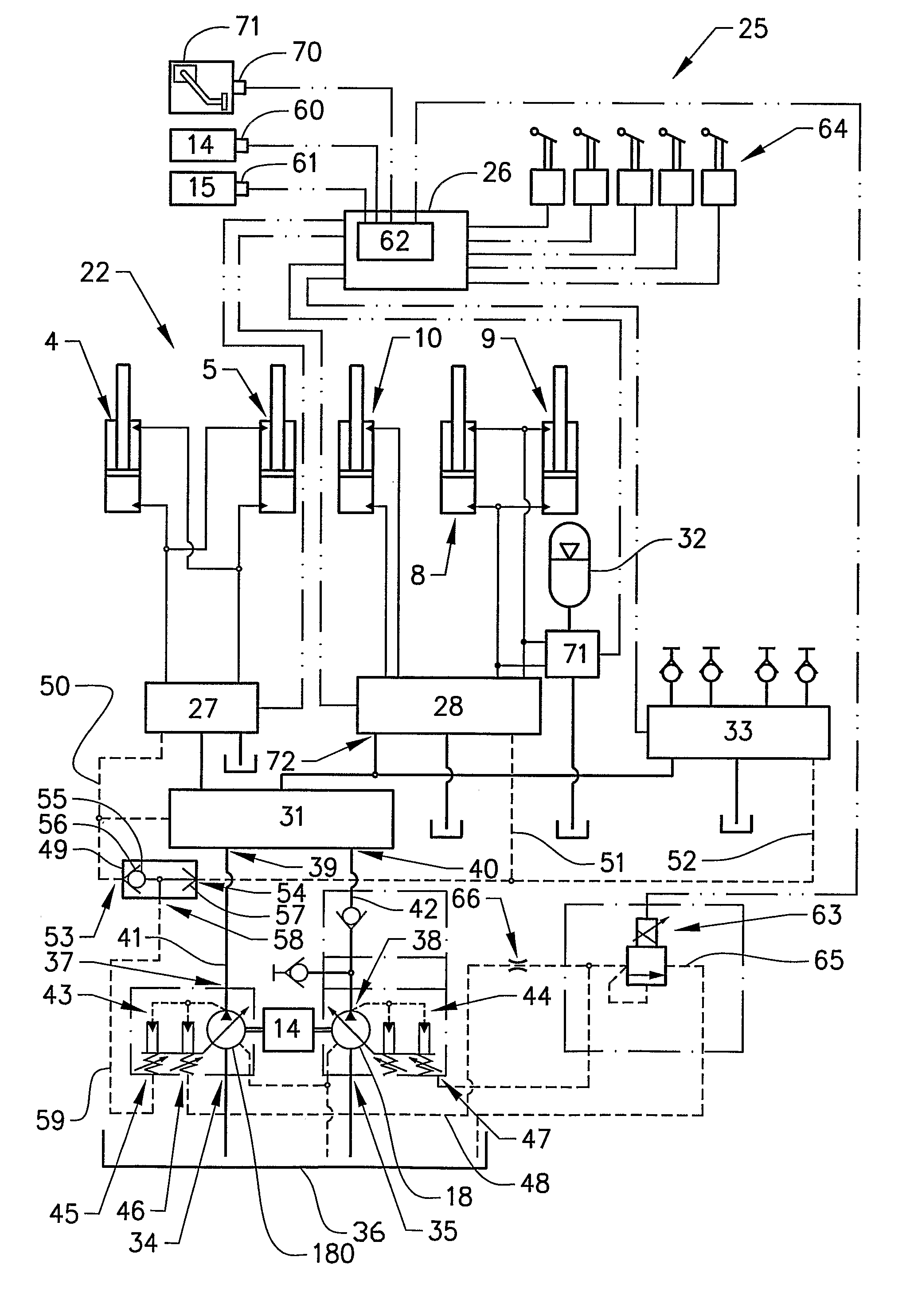
[0046] the engine speed is sensed. When the engine speed falls to a predetermined minimum, the control unit 26 will output a signal with a level as a function of the detected engine speed. Said detection means may also comprise means 70 for detecting the position of an accelerator pedal 71. Therefore, as an alternative, the control unit 26 will output a signal with a level as a function of both the detected engine speed and the detected position of an accelerator pedal 71.

second embodiment

[0047] the turbocharger pressure is sensed. When the turbocharger pressure falls to a predetermined minimum, the control unit 26 will output a signal with a level as a function of the detected turbocharger speed. As an alternative, the control unit 26 will output a signal with a level as a function of both the detected turbocharger pressure and the detected position of an accelerator pedal 71.

third embodiment

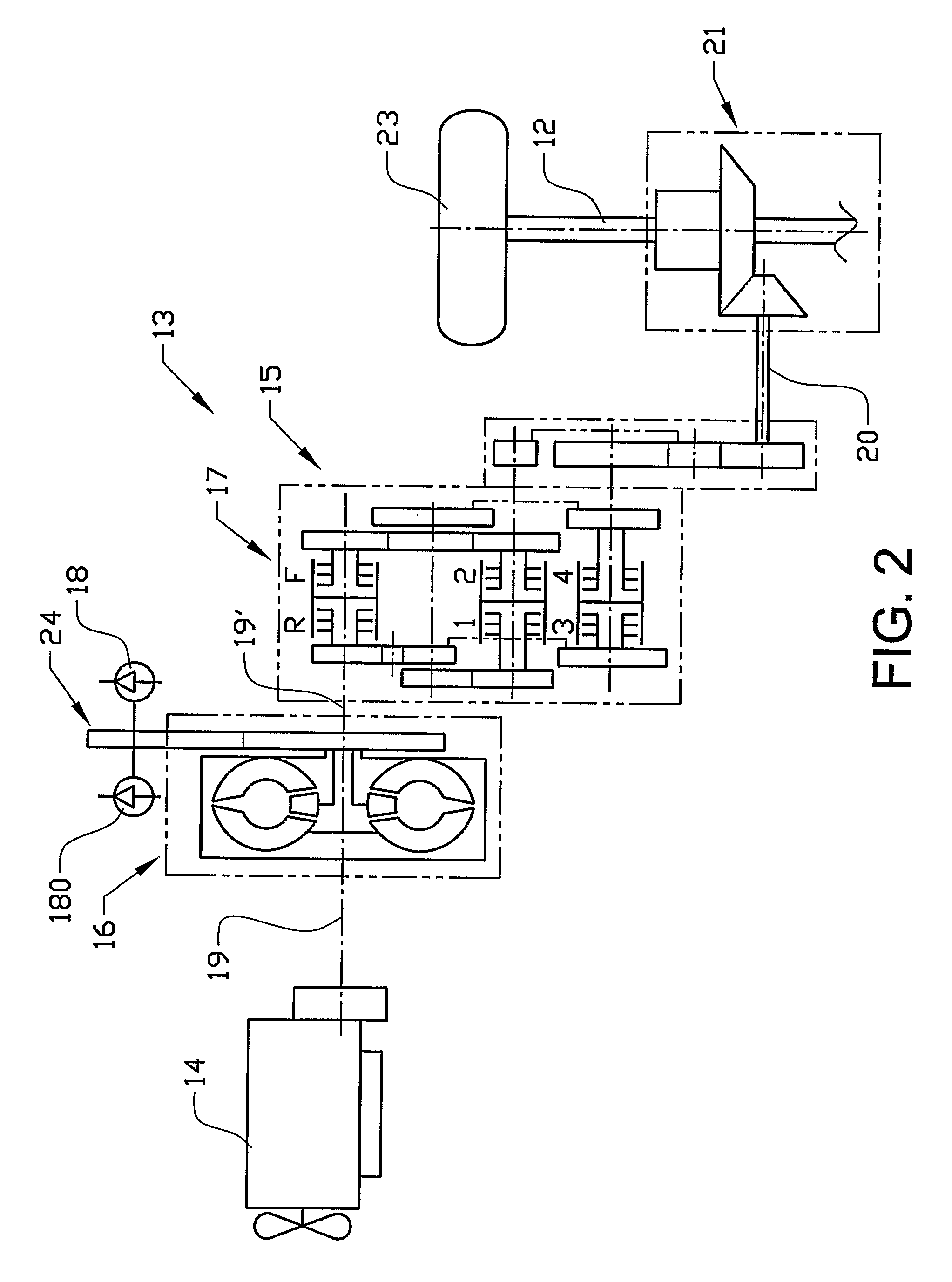
[0048] a driveline torque or output power is sensed. In this embodiment the engine torque is sensed. The pressure in a clutch in the gear box is used as a measure of the engine torque. Such clutch pressure signals are directly related to the torque being transmitted by the clutch to the wheels and by the wheels to the ground. When the torque falls to a predetermined minimum, the control unit 26 will output a signal with a level as a function of accessible engine torque. As an alternative, the control unit 26 will output a signal with a level as a function of both accessible engine torque and the detected position of an accelerator pedal 71.

[0049] Said detection means further comprises means 61 for detecting a gear state in the gear box 15. More specifically, the detection means 61 detects a neutral state in the gear box 15. If the driver uses the hydraulic system 22 for a certain work operation when the vehicle is standing still, the driver normally puts the gear in the neutral sta...


PUM


Abstract

An arrangement for controlling a work vehicle including a hydraulic system that includes at least one pump and at least one actuator operatively driven by hydraulic fluid delivered from the pump is provided. At least a first pump is a variable displacement pump. The system is of load-sensing type in that the pump displacement is controlled by a pilot pressure representing a load exerted on the system. The arrangement includes an arrangement for reducing the pilot pressure delivered to the first pump so that the first pump displacement is regulated down when there is a need for limiting hydraulic power consumption.

Description

BACKGROUND AND SUMMARY [0001] The present invention relates to an arrangement for controlling a work vehicle comprising a hydraulic system. The hydraulic system comprises at least one pump and at least one actuator operatively driven by hydraulic fluid delivered from said pump, wherein at least a first pump is a variable displacement pump. The system is of load-sensing type in that the pump displacement is controlled by a pilot pressure representing a load exerted on the system. [0002] The pump is normally operatively driven by an internal combustion engine arranged for propelling the work vehicle. [0003] The term work vehicle comprises different types of material handling vehicles like construction machines, such as a wheel loader, a backhoe loader, a motor grader and an excavator. The invention will be described below in a case in which it is applied in a wheel loader. This is to be regarded only as an example of a preferred application. [0004] Said actuator may be a linear actuat...

Claims


Application Information

Patent Timeline
Patent Type & Authority Applications(United States)
IPC IPC(8): E02F9/22F16H61/46F04B49/02F15BF16H61/475
CPCE02F9/2217F16H61/475E02F9/2253E02F9/2292E02F9/2296F04B49/022F15B11/165F15B2211/20523F15B2211/20553F15B2211/20576F15B2211/253F15B2211/26F15B2211/654F15B2211/6652F15B2211/6655F15B2211/781E02F9/2221E02F9/22F15B11/16F16H61/46E02F9/20
Inventor VIGHOLM, BOFRANSSON, PATRIKSJOGREN, KJELLSALOMONSSON, STEFAN HARALD
Owner VOLVO CONSTR EQUIP HLDG (SWEDEN) AB
Why Eureka
Try Eureka