
Eureka
For R&D, Eureka makes reading and utilizing patents & technical documents easy.
Eureka AIR
Designed for self-driven R&D workflows. Generate viable solutions, solve complex R&D challenges, empower your innovation with AI.

Eureka Materials
Designed for material experts only. Revolutionize your material R&D, from search, analyze, to developing new materials.

TechResearch
Generate reliable direction feasibility study reports for your R&D in just a few steps.

TechSeek
Discover and master advanced knowledge NOW. Basics, ideas, possibilities, all at once.

TechMind
As an expert in R&D Theories, TechMind can generates customized viable solutions instantly.

TechRisk
Analyze your overall solution with one click, know your potential R&D risks in advance.

TechMonitor
Get weekly tech updates, stay abreast of the latest tech innovations and key insights.
Heat accumulator and engine
- Summary
- Abstract
- Description
- Claims
- Application Information
AI Technical Summary
Benefits of technology
Problems solved by technology
Method used
Image

Examples
first embodiment
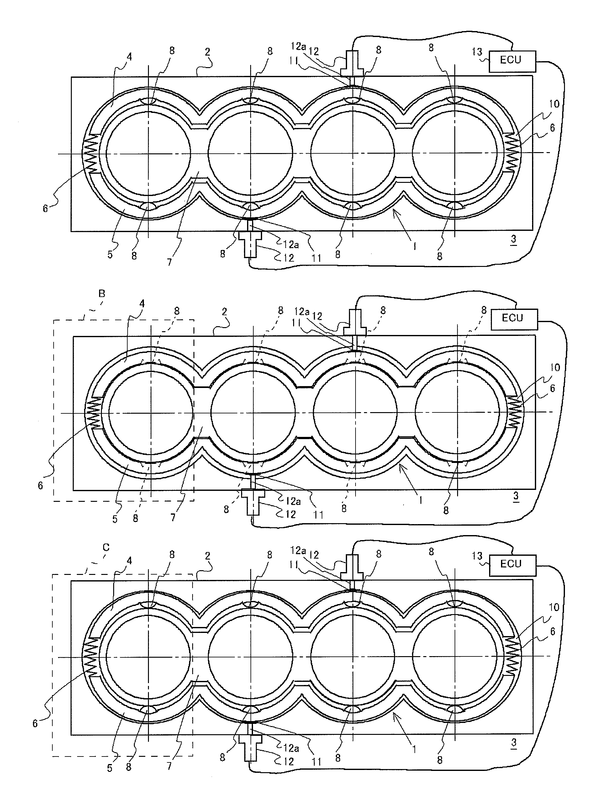
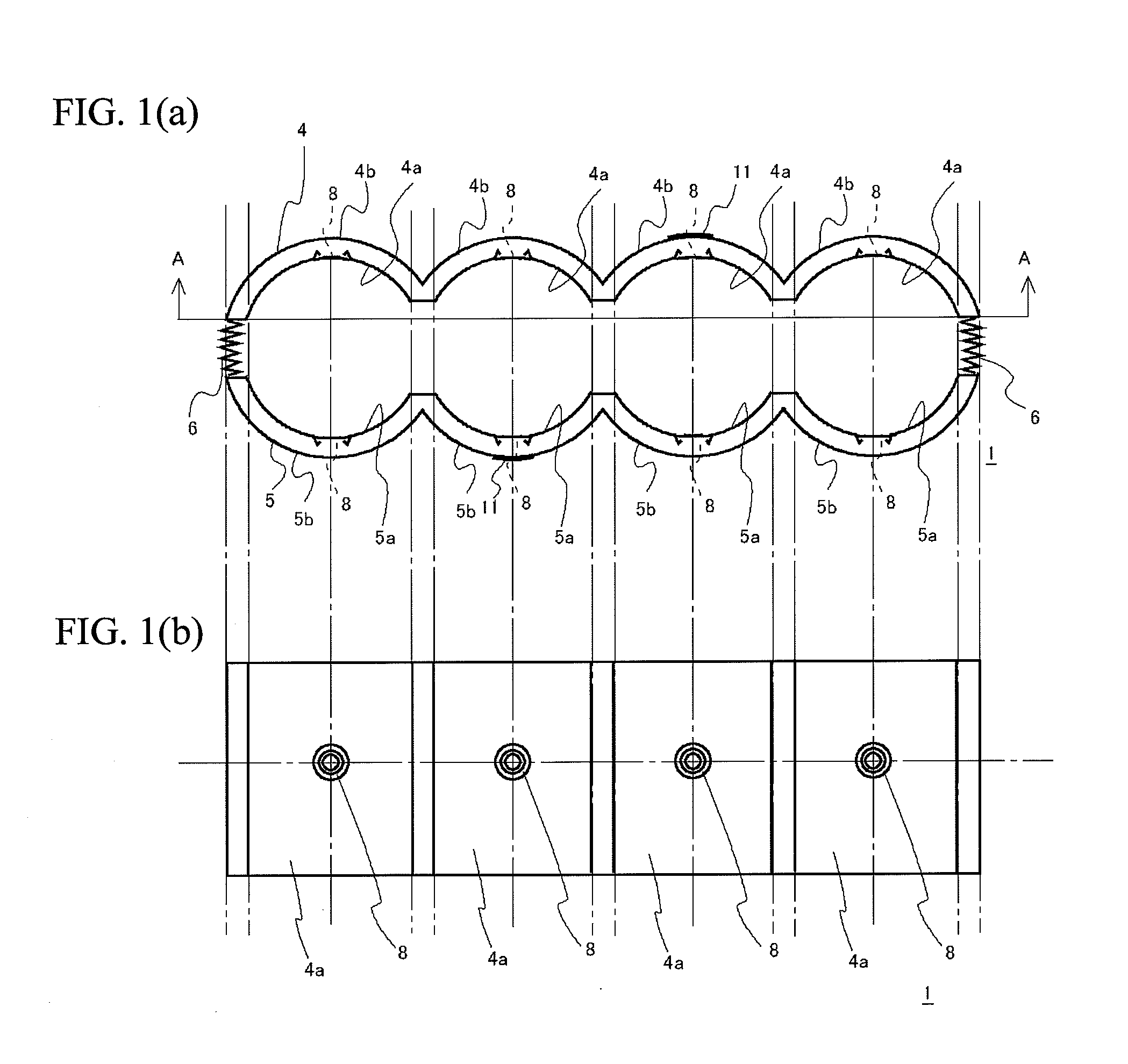
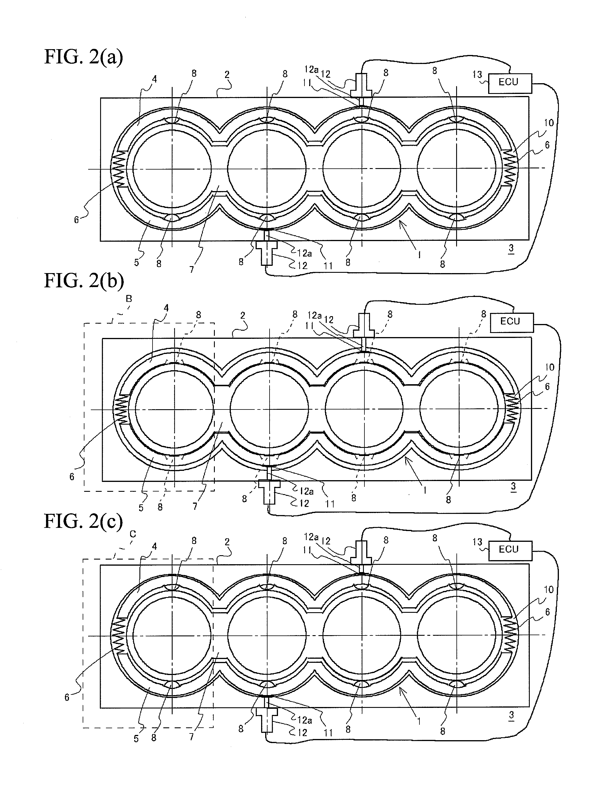
[0040]FIG. 1(a) is a plane view of a heat accumulator 1 according to the present invention. FIG. 1(b) is a cross-sectional view taken along a line A-A in FIG. 1(a). FIGS. 2(a) to (c) are all views showing the schematic structure of an engine 3 incorporating the heat accumulator 1 in a cylinder block 2, and views as seen from a cylinder head mounting side of the cylinder block 2 with the cylinder head removed. FIGS. 2(a) to (c) show different states of the heat accumulator 1 during operation. FIG. 3 is an expanded view showing a region B in FIG. 2(b) circled by a broken line. FIG. 4 is an expanded view showing a region C in FIG. 2(c) circled by a broken line. FIG. 5 is a cross-sectional view taken along a line D-D in FIG. 3. FIG. 6 is a cross-sectional view taken along a line E-E in FIG. 4. Note that the engine 3 in the present embodiment is a four-cylinder engine.
[0041]As the figures show, the heat accumulator 1 is formed by connecting a first container 4 and a second container 5 vi...
second embodiment
[0055]A second embodiment will be described next with reference to FIGS. 7 to 10. FIG. 7 is a plane view of a heat accumulator 21 according to the second embodiment. FIGS. 8(a) and (b) are both views showing the schematic structure of the engine 3 incorporating the heat accumulator 21 in the cylinder block 2, and views as seen from a cylinder head mounting side of the cylinder block 2 with the cylinder head removed. FIGS. 8(a) and (b) show different states of the heat accumulator 21 during operation. FIG. 9 is an expanded view showing a region F in FIG. 8(a) circled by a broken line. FIG. 10 is an expanded view showing a region G in FIG. 8(b) circled by a broken line. Note that the engine 3 in the present embodiment is a four-cylinder engine, and along with the cylinder block 2, is identical to the engine 3 in the first embodiment.
[0056]As the figures show, the heat accumulator 21 is formed by connecting a first container 22 and a second container 23 via a connecting member 24, whic...
third embodiment
[0069]A third embodiment will be described next with reference to FIGS. 11 to 14. FIG. 11 is a plane view of a heat accumulator 31 according to the third embodiment. FIGS. 12(a) and (b) are both views showing the schematic structure of the engine 3 incorporating the heat accumulator 31 in the cylinder block 2, and views as seen from a cylinder head mounting side of the cylinder block 2 with the cylinder head removed. FIGS. 12(a) and (b) show different states of the heat accumulator 31 during operation. FIG. 13 is an expanded view showing a region H in FIG. 12(a) circled by a broken line. FIG. 14 is an expanded view showing a region I in FIG. 12(b) circled by a broken line. Note that the engine 3 in the present embodiment is a four-cylinder engine, and along with the cylinder block 2, is identical to the engine 3 in the first and second embodiments.
[0070]As the figures show, the heat accumulator 31 is formed by connecting the first container 22 and the second container 23 via a sprin...
PUM
 Abstract
Description
Claims
Application Information
 - R&D Engineer
- R&D Manager
- IP Professional
- Industry Leading Data Capabilities
- Powerful AI technology
- Patent DNA Extraction
Browse by: Latest US Patents, China's latest patents, Technical Efficacy Thesaurus, Application Domain, Technology Topic, Popular Technical Reports.
© 2024 PatSnap. All rights reserved.Legal|Privacy policy|Modern Slavery Act Transparency Statement|Sitemap|About US| Contact US: help@patsnap.com