
Mixing device, method and program

a technology of mixing device and mixing method, applied in the field of sound mixing technology, can solve the problems of difficult adjustment for users, complicated manipulation of the music mixing system, and inability of ordinary users (listeners) to increase or decrease the sound volume of a particular part they want to hear, etc., to achieve simple manner, narrow and expand the directional angle range

Active Publication Date: 2009-02-05
JAPAN SCI & TECH CORP
View PDF5 Cites 27 Cited by
  • Summary
  • Abstract
  • Description
  • Claims
  • Application Information

AI Technical Summary

Benefits of technology

[0009]A specific object of the present invention is therefore to provide a mixing system in which a listener can readily increase or decrease the sound volume of a desired sound source specified by the listener in a condition where a plurality of virtual sound sources are fixedly located, a method therefor, and a computer program therefor.Means of Solving the Problem
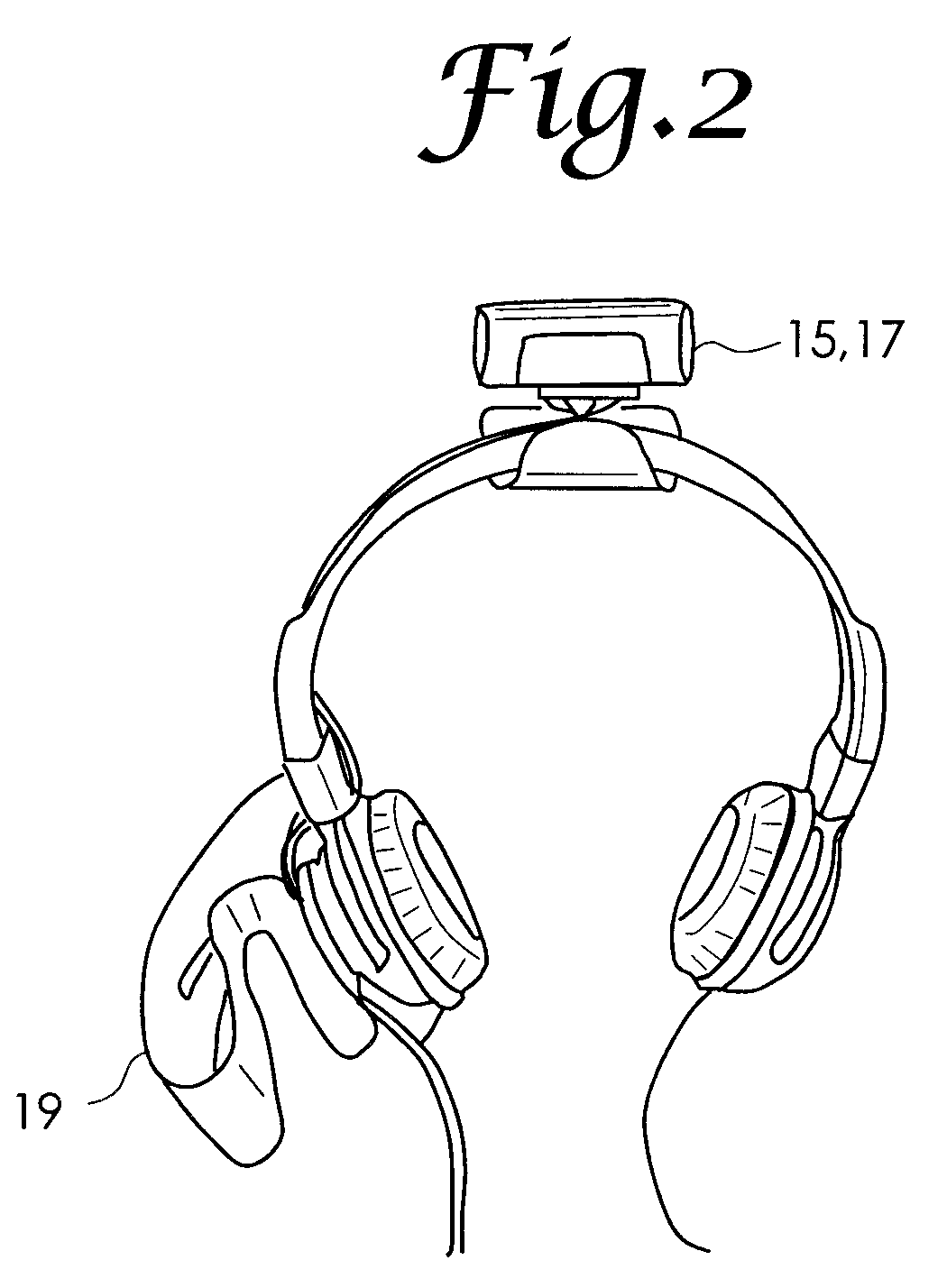
[0018]It is arbitrary what kind of sensor is used as the directional angle detection sensor and the elevation angle detection sensor. For example, when an electronic compass, a gyro sensor, a tilt sensor capable of detecting a tilt angle in triaxial directions, or an acceleration sensor is employed, the directional angle detection sensor and the elevation angle detection sensor may be constituted from one sensor component, thereby reducing the number of parts.

Problems solved by technology

It is impossible for users to adjust them even when they want to increase the sound volume of a specific sound source, for example, when users want to increase the sound volume of the first violin in a piece of classical music without changing the sound volume of the music piece itself.
Actually, however, manipulation of the music mixing system is too complicated for amateur users to operate intuitively.
Incidentally, a mixing apparatus with a recording / reproducing function disclosed in Japanese Patent No. 3633459 (refer to Patent Reference 1) is complicated in operation, and it is not easy for ordinary users (listeners) to increase the sound volume of a particular part they want to hear, or decrease the sound volume of a particular part they do not want to hear when listening to the music.
For example, it is difficult to quickly perform a series of adjusting operations to increase the sound volume of a violin, to set the panpot at the center of two speakers (setting the sound volume ratio of the violin output from the left / right speakers to 1 / 1), and adjusting the localization or panpots of the other musical instruments by slightly decreasing the sound volumes thereof when the violin solo part has started.
However, by this method, it is difficult to for a listener to arrange near the listener the a particular part of the music that the listener wants to hear and to increase the sound volume of that part, or to arrange apart from the listener a particular part that the listener does not want to hear and to decrease the sound volume of that part while the listener is listening to the music.
With existing amplifiers which are capable of separately adjusting an amplification factor for either side speaker, and existing vocal canceling machines, namely, equipment capable of removing a sound localized at the center, it may be possible to partially change the sound volumes and panpots of respective parts of the mixed-down music, but such apparatuses are not practically usable in adjusting the sound volume or localization of a specific sound source.

Method used


Image

  • Mixing device, method and program
  • Mixing device, method and program
  • Mixing device, method and program

Examples


Embodiment Construction

[0040]Embodiments of the present invention will now be described in detail hereinbelow by referring to the accompanying drawings.

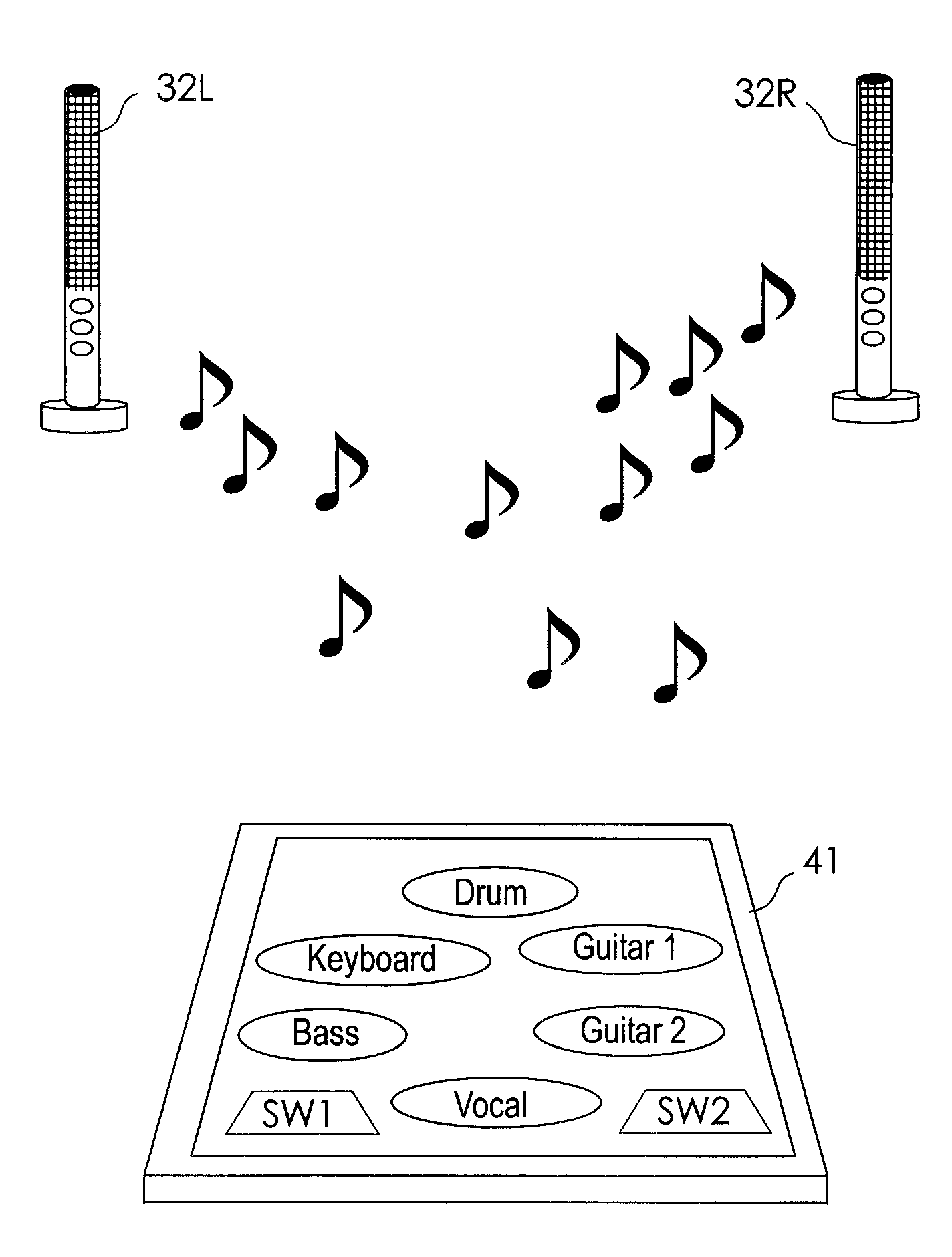
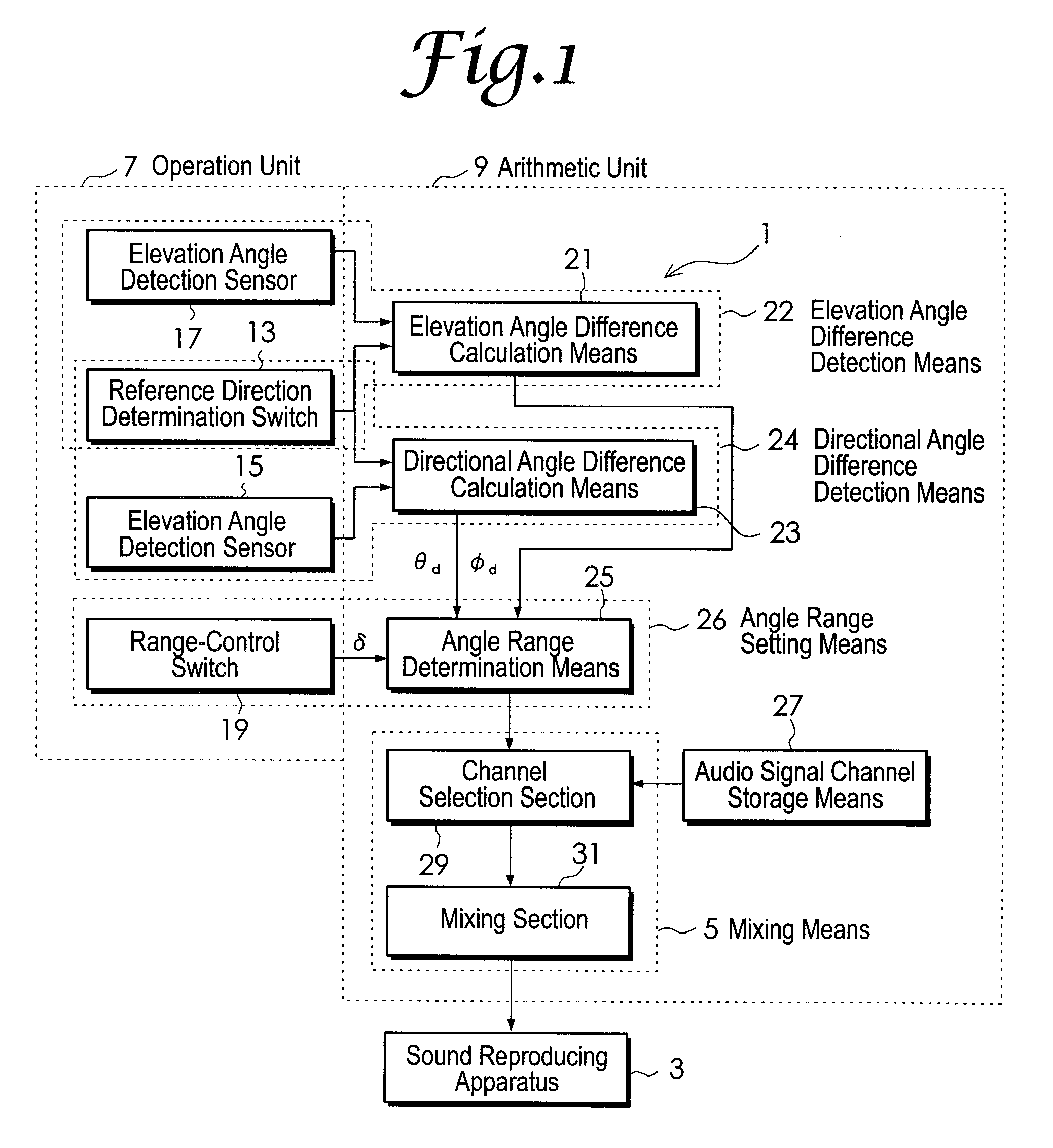
[0041]FIG. 1 is a block diagram showing an example of schematic configuration of a mixing system to implement a mixing method of the present invention. A mixing system 1 of the present embodiment includes mixing means 5 for mixing a plurality of audio signals and outputting a mixed audio signal to a sound reproducing apparatus 3 which produces a plurality of virtual sound sources around a listener. The plurality of audio signals are supplied from a plurality of audio signal channels respectively associated with the plurality of virtual sound sources. The sound reproducing apparatus 3 described here is what is called audio equipment, which is a publicly known apparatus capable of creating a plurality of virtual sound sources in a three-dimensional space around the listener. The mixing system 1 further includes an operation unit 7 operated by the listener an...


PUM


Abstract

In a situation where a plurality of virtual sound sources are fixedly located, a mixing system allows a listener to increase or decrease the sound volumes of the virtual sound sources with a simple operation. Directional angle difference detection means 24 detects a directional angle difference between a predetermined reference directional angle and an indicated directional angle which is determined by the listener by pointing with an operation unit 7 a certain direction in a virtual space where the virtual sound sources exist. Mixing means 5 mixes a plurality of audio signals supplied from a plurality of audio channels and outputs a mixed audio signal without adjustment, when the directional angle difference is zero degrees. When the directional angle difference is other than zero degrees, the mixing means 5 creates a situation where the plurality of virtual sound sources are fixedly located with respect to the reference directional angle, and mixed the plurality of audio signals so that the sound volumes of one or more sound sources arranged in a direction of the indicated directional angle may be larger than those of the one or more sound sources at the time that the directional angle difference is zero degrees.

Description

TECHNICAL FIELD[0001]The present invention relates to sound mixing technology, and particularly relates to a mixing system, mixing method and mixing program which allow listeners to control the mixing.BACKGROUND ART[0002]A human being has the ability to know the location of a sound source based on a plurality of factors such as interaural intensity difference (IID), interaural time difference (ITD), and changes in frequency characteristics by using two ears. Generally, music recorded on a compact disc and so on has been mixed down using a music mixing system by adjusting the sound volumes and localization or panpots of a plurality of sound sources (musical instruments etc.) so that the respective sound sources are well separated for ready listening. Accordingly, when the mixed-down music is reproduced, the sound volumes and localization of the plurality of sound sources have already been fixed. It is impossible for users to adjust them even when they want to increase the sound volum...

Claims


Application Information

Patent Timeline
IPC IPC(8): H04R5/033H04R5/00
CPCH04R3/12H04S2400/11H04S7/304
Inventor HAMANAKA, MASATOSHIIKETUKI, YUUYA
Owner JAPAN SCI & TECH CORP
Learn More