

Hydrodynamic bearing unit
- Summary
- Abstract
- Description
- Claims
- Application Information
AI Technical Summary
Benefits of technology
Problems solved by technology
Method used
Image

Examples
examples
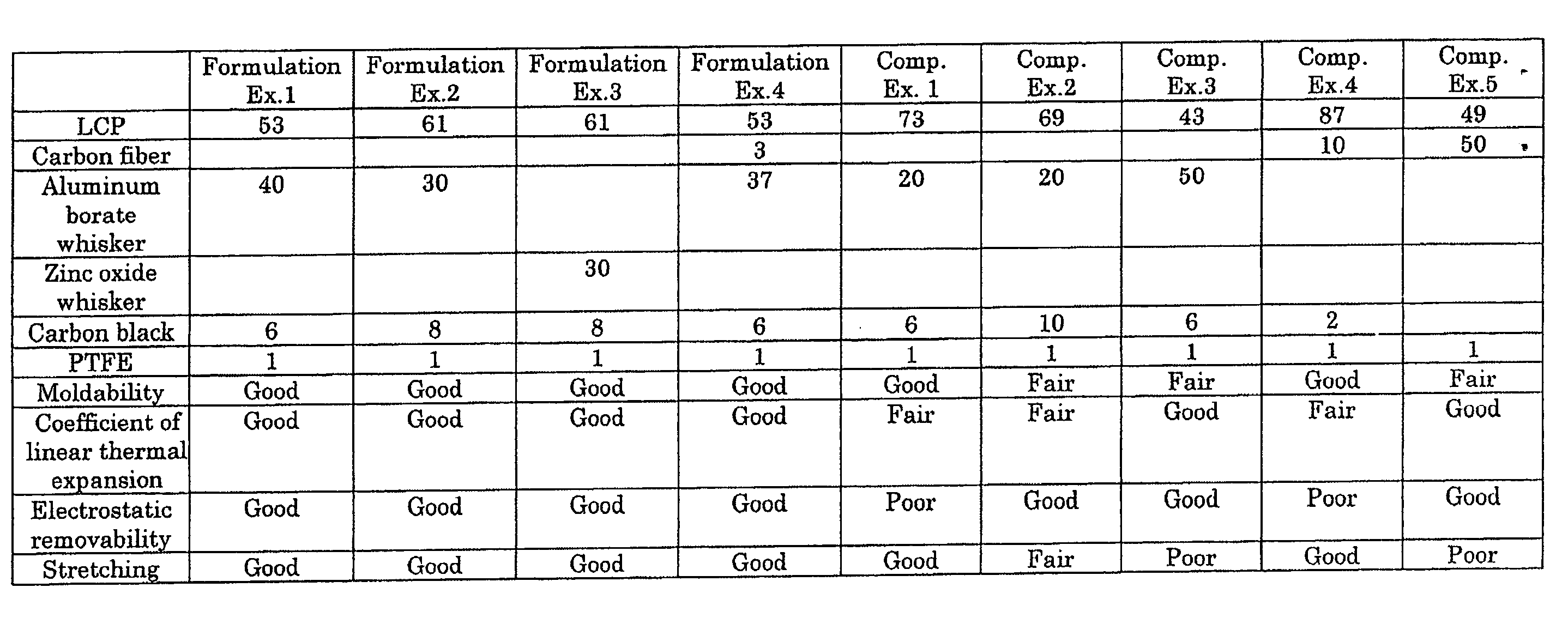
[0057]To demonstrate the advantages of the present invention, the housing 7 was formed by using liquid-crystalline polymer (LCP) as a base material and fillers at different formulation ratios. The fillers were carbon fiber, inorganic fiber (such as aluminum borate whisker, zinc oxide whisker) and carbon black. The characteristics required for the housing 7 of the resulting housings were compared.
[0058]In this Example, the following products were used: H3110 manufactured by Nippon Steel Chemical Co., Ltd. as an ester-based lubricating oil; a powdery liquid-crystalline polymer as liquid-crystalline polymer (LCP) (preparation method will be described below); Besfight HTA-C6-E manufactured by Toho Tenax Co., Ltd. as a carbon fiber; Alborex Y manufactured by Shikoku Corporation as an aluminum borate whisker; Panatetra WZ-0501 manufactured by Matsushita Electric Industrial Co., Ltd. as a zinc oxide whisker; and Ketchen Black EC manufactured by Lion Corporation as carbon black. Polytetrafl...
PUM
 Abstract
Description
Claims
Application Information