Exhaust treatment system with an oxidation device for NO2 control

a technology of exhaust treatment system and oxidation device, which is applied in the direction of separation process, machine/engine, mechanical apparatus, etc., can solve the problem of reducing the number of no2 /sub>

Inactive Publication Date: 2009-02-05
CATERPILLAR INC
View PDF38 Cites 116 Cited by
  • Summary
  • Abstract
  • Description
  • Claims
  • Application Information

AI Technical Summary

Problems solved by technology

As a result, there is a risk of providing too much NO2 compared to NO.

Method used


Image

  • Exhaust treatment system with an oxidation device for NO2 control
  • Exhaust treatment system with an oxidation device for NO2 control
  • Exhaust treatment system with an oxidation device for NO2 control

Examples


Embodiment Construction

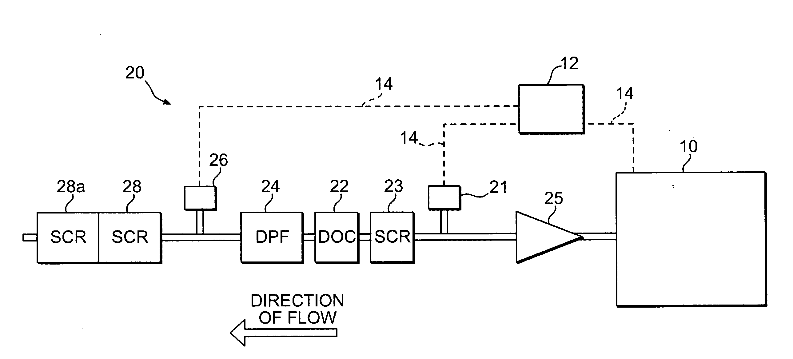
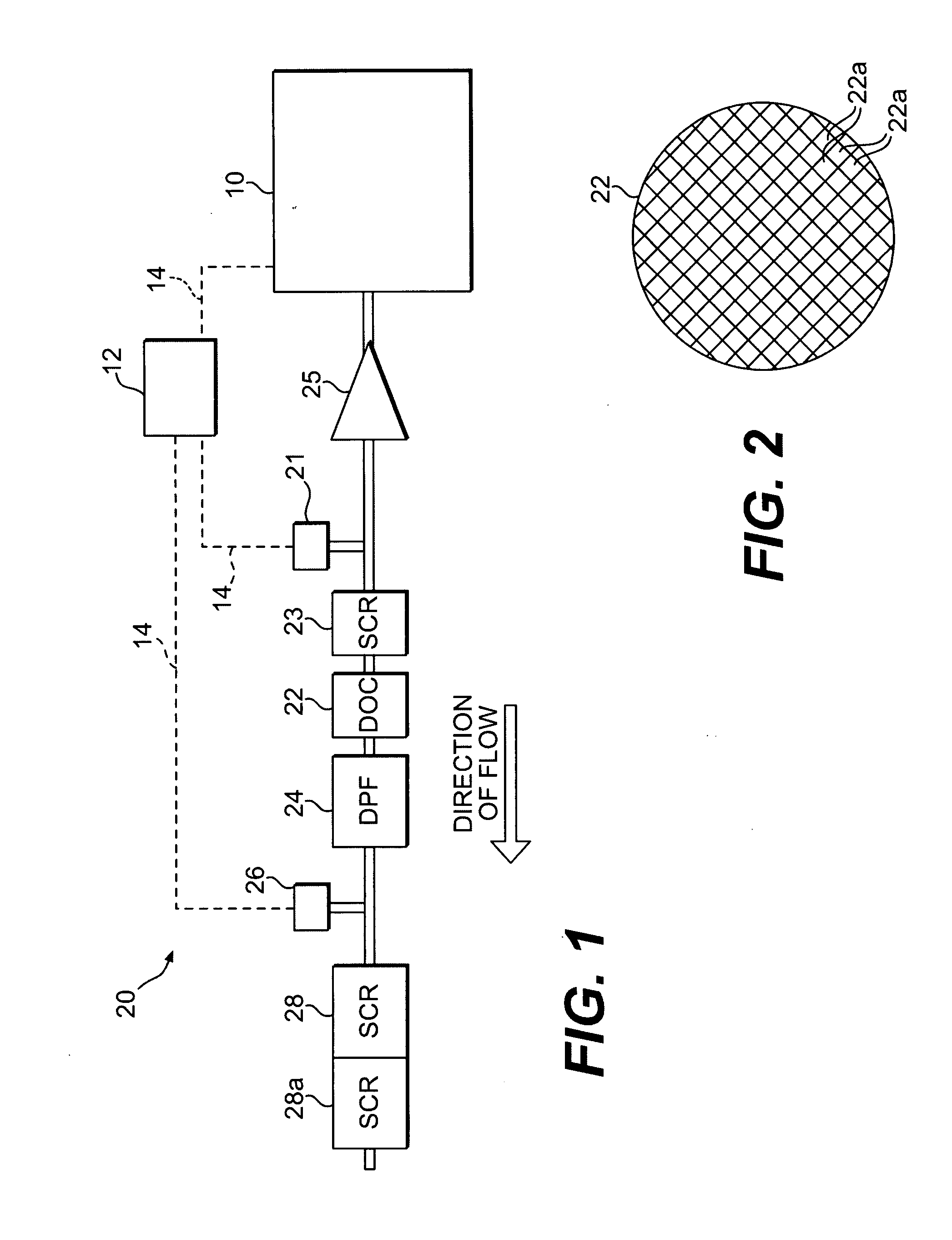
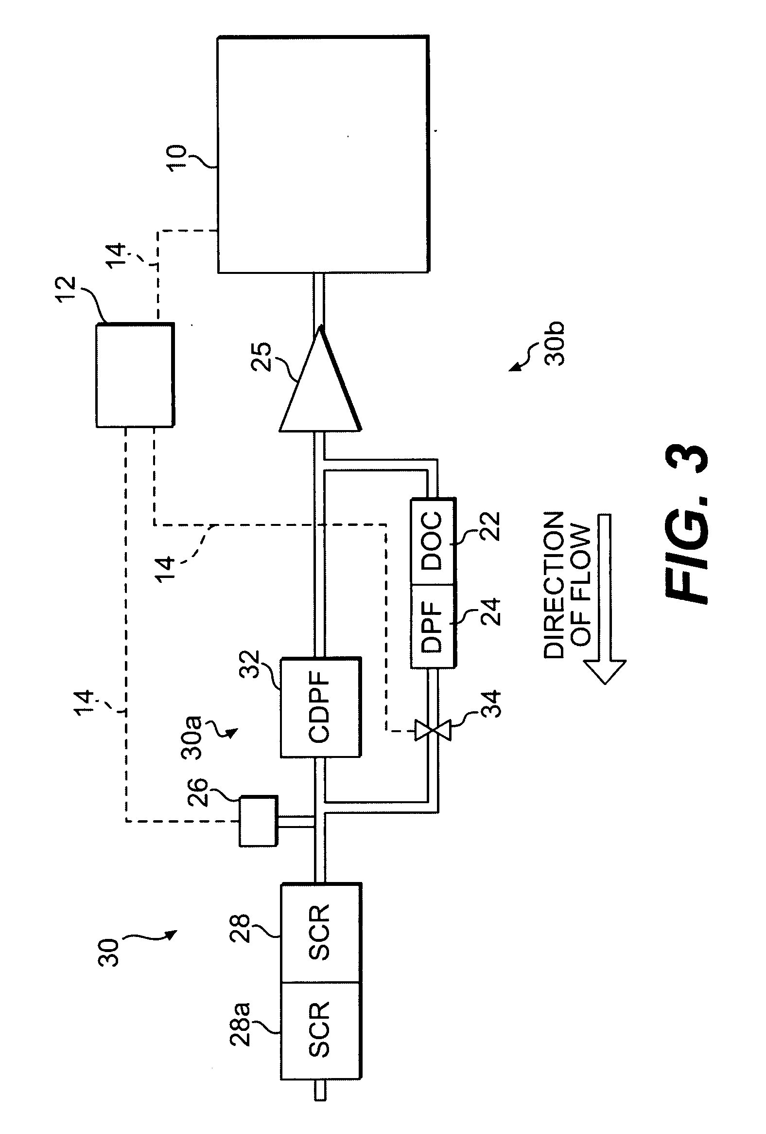
[0020]Reference will now be made in detail to exemplary embodiments, which are illustrated in the accompanying drawings. Wherever possible, the same reference numbers will be used throughout the drawings to refer to the same or like parts.

[0021]As shown in FIG. 1, a power source, such as an engine 10, of a machine is provided. The disclosed embodiment may be applicable to various types of machines such as, for example, a fixed or mobile machine that performs some type of operation associated with an industry such as mining, construction, farming, transportation, power generation, tree harvesting, forestry, or any other industry known in the art. The engine 10 may be an internal combustion engine, such as, for example, a diesel engine, a gasoline engine, a gaseous fuel-powered engine, or any other engine apparent to one skilled in the art. The engine 10 may alternatively be another source of power such as a furnace or any other suitable source of power for a powered system such as a ...


PUM

PropertyMeasurementUnit
temperatureaaaaaaaaaa

Abstract

An exhaust treatment system includes an oxidation device having a plurality of channels through which a flow of exhaust flows. A first portion of the channels of the oxidation device are coated with catalytic material for converting NO to NO2 and a second portion of the channels are uncoated with the catalytic material. The exhaust treatment system also includes a selective catalytic reduction device disposed downstream from the oxidation device. The selective catalytic reduction device is configured to receive the flow of exhaust passing through the oxidation device.

Description

TECHNICAL FIELD[0001]The present disclosure relates generally to an exhaust treatment system, and more particularly, to an exhaust treatment system with NO2 control.BACKGROUND[0002]Internal combustion engines, including diesel engines, gasoline engines, gaseous fuel-powered engines, and other engines known in the art, may exhaust a complex mixture of air pollutants. The air pollutants may be composed of gaseous and solid compounds, including particulate matter, nitrogen oxides (NOx), and sulfur compounds. Due to heightened environmental concerns, exhaust emission standards have become increasingly stringent. The amount of pollutants emitted from an engine may be regulated depending on the type, size, and / or class of engine. One method that has been implemented by engine manufacturers to comply with the regulation of NOx exhausted to the environment has been to implement a strategy called selective catalytic reduction (SCR).[0003]SCR is a process by which gaseous or liquid reductant ...

Claims


Application Information

Patent Timeline
Patent Type & Authority Applications(United States)
IPC IPC(8): F01N3/20
CPCF01N3/0231F01N13/0093F01N3/027F01N3/035F01N3/106F01N3/2066F01N3/208F01N2510/0682F01N2560/026F01N2560/06F01N2610/02Y02T10/24F01N13/009F01N13/011F01N3/025Y02T10/12
Inventor ROBEL, WADE J.CHAVANNAVAR, PRAVEEN SHIVSHANKARHARDY, WILLIAM LYLESCHROEDER, ERIC LEE
Owner CATERPILLAR INC
Why Eureka
Try Eureka