Connector and connector assembly

a technology of connectors and connector parts, applied in the direction of incorrect coupling prevention, coupling device connection, electrical equipment, etc., can solve the problems of not being able to confirm the position of the detector, forgetting to move the detector, and affecting so as to achieve the effect of improving the reliability of the connection detection function

Inactive Publication Date: 2009-02-05
SUMITOMO WIRING SYST LTD
View PDF19 Cites 31 Cited by
  • Summary
  • Abstract
  • Description
  • Claims
  • Application Information

AI Technical Summary

Benefits of technology

[0010]The invention relates to a connector with a housing capable of accommodating at least one terminal fitting. At least one detector is assembled with the housing and can move from a standby position to a detection position if the housing is connected properly with a mating housing. However, the detector is prevented from moving to the detection position if the housing is connected only partly with the mating housing. The detector has at least one opening and a background color seen through the opening differs when the detector at the standby position than when the detector is at the detection position. Thus, the arrival of the detector at the detection position can be confirmed clearly. As a result, an operator will not forget to move the detector, and the reliability of a connection detecting function is improved.

Problems solved by technology

However, there are cases where the position of the detector cannot be confirmed clearly or the locking sound may be drowned out by noise at an operation site.
Thus, there is a likelihood of forgetting to move the detector and, hence, impairing the connection detecting function of the connector.
Additionally, the resilient piece is disengaged from the lock arm by interference with the lock projection.

Method used


Image

  • Connector and connector assembly
  • Connector and connector assembly
  • Connector and connector assembly

Examples


first embodiment

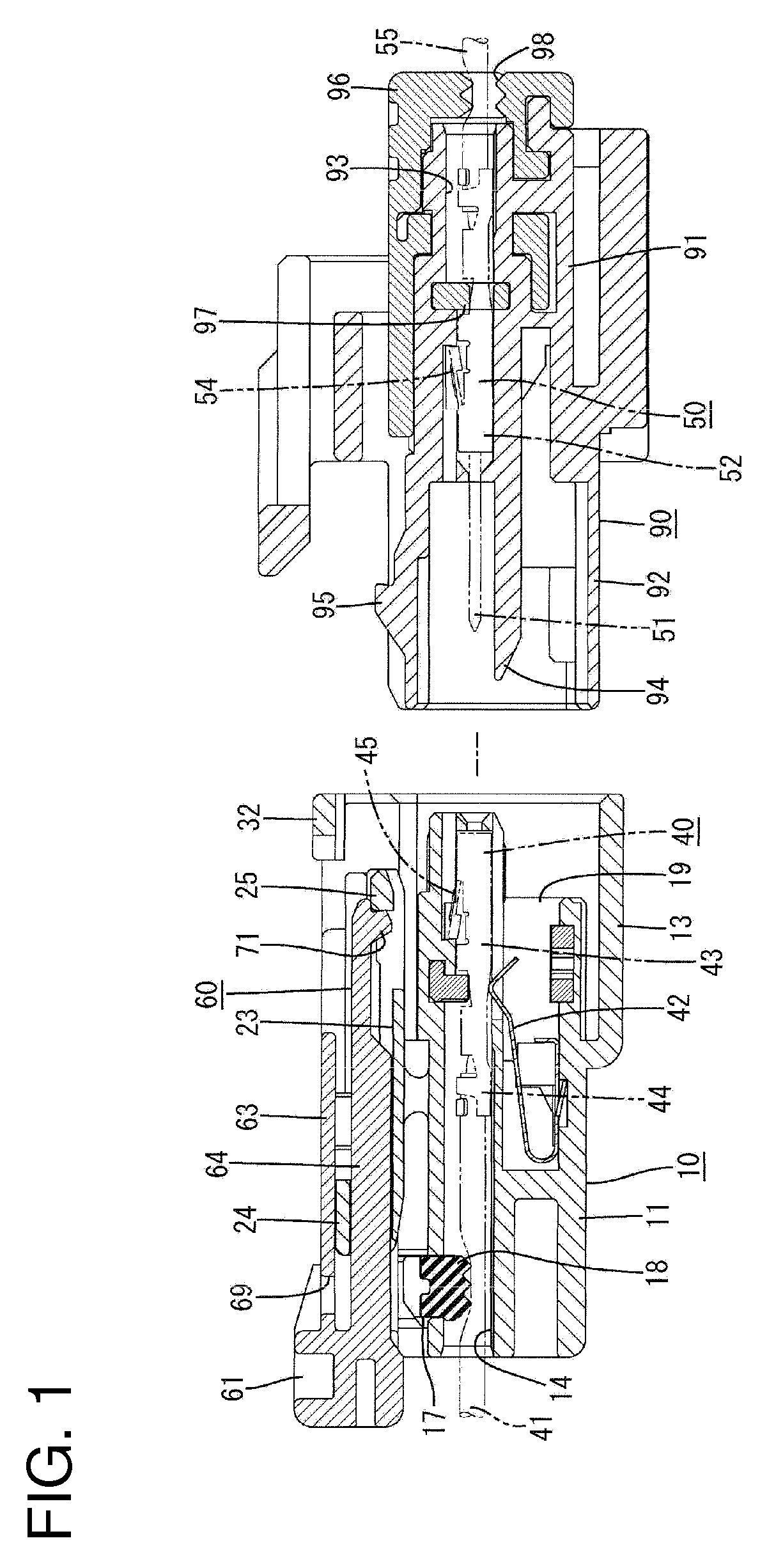
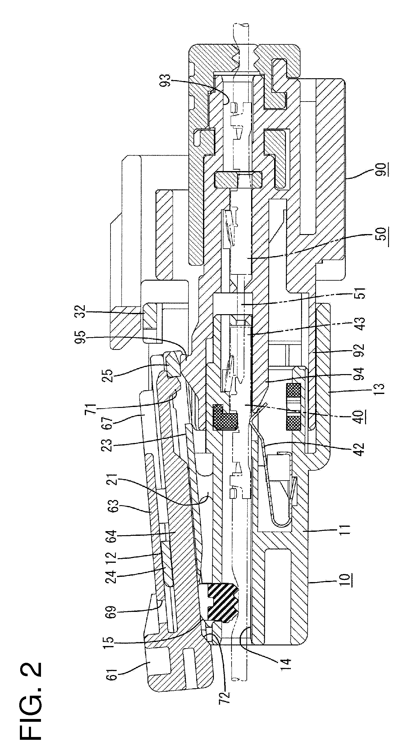
[0045]the invention is described with reference to FIGS. 1 to 10. A connector of this embodiment is provided with a housing 10, one or more female terminal fittings 40 and a detector 60. The housing 10 is connectable with a mating housing 90 and the detector 60 is movable between a standby position SP and a detection position DP with respect to the housing 10. In the following description, ends of the housings 10, 90 to be connected are referred to as front ends concerning forward and backward directions.

[0046]The male housing 90 is made e.g. of synthetic resin and includes a terminal accommodating portion 91 for accommodating male terminal fittings 50 and a tubular receptacle 92 that projects forward from the front of the terminal accommodating portion 91. Cavities 93 are formed in the terminal accommodating portion 91 and accommodate male terminal fittings 50. Tabs 51 of the male terminal fittings 50 project forward from the front surface of the cavities 93 and into the receptacle...

second embodiment

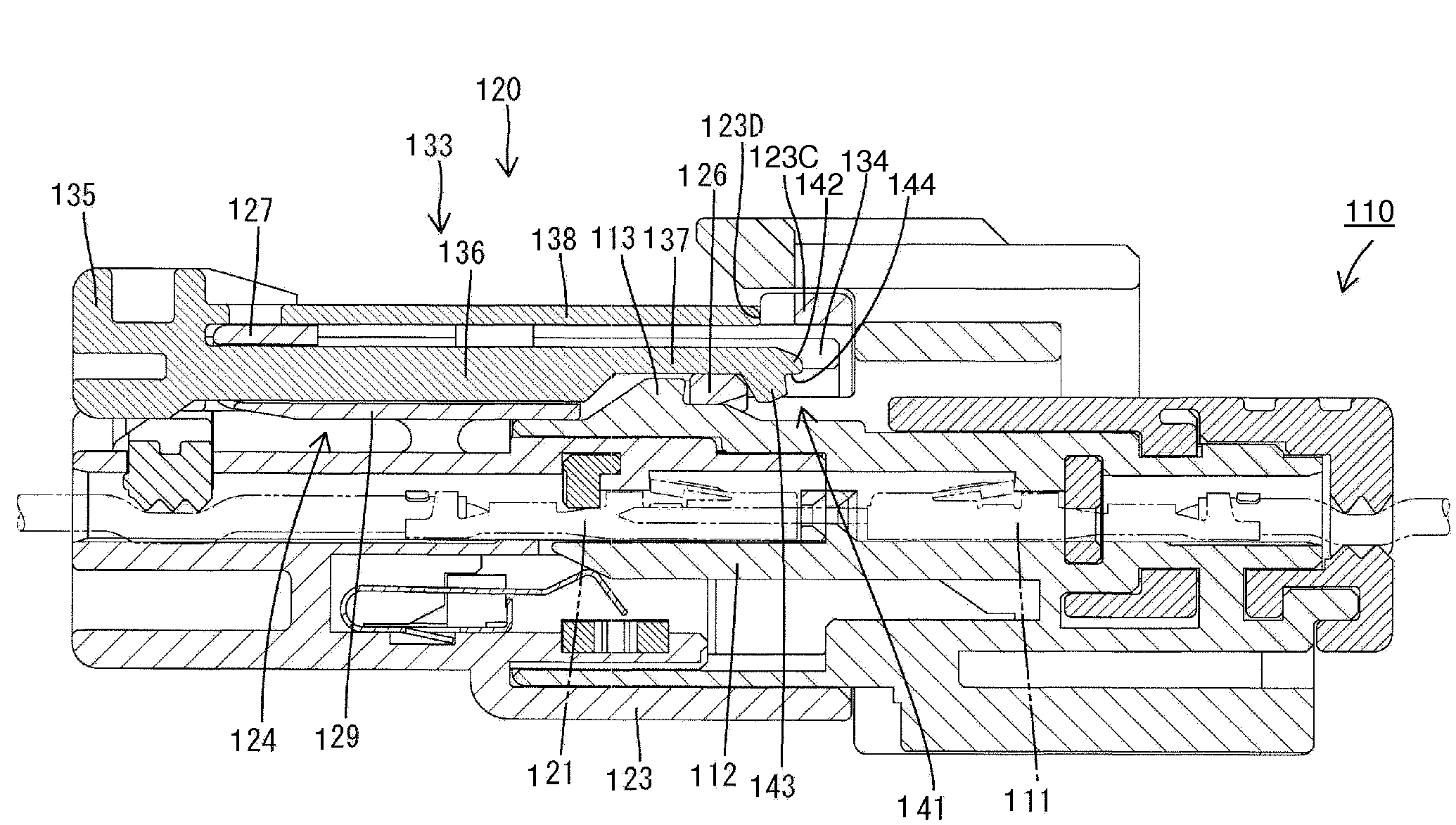
[0077]the invention is described with reference to FIGS. 11 to 21. A connector of this embodiment is provided with a first housing 110 having male terminal fittings 111 mounted therein and a second housing 120 having female terminal fittings 121 mounted therein. It should be noted that, in the following description, forward and backward directions are the same directions as those parallel to a connecting direction of the housings 110, 120.

[0078]The first housing 110 is made e.g. of synthetic resin and includes a tubular receptacle 112 projecting forward in the same direction as the connecting direction with the second housing 120. A lock 113 projects from the upper surface (outer surface) of the upper wall of the receptacle 112.

[0079]The second housing 120 is made unitarily e.g. of synthetic resin and has a block-shaped terminal holding portion 122 and a rectangular tubular fitting 123 that surrounds a front portion of the terminal holding portion 122. The female terminal fittings 1...


PUM


Abstract

A detector (60) is assembled with a lock arm (12) of a housing (10) to be movable between a standby position and a detection position. The detector (60) can move from the standby position to the detection position when the housing (10) is connected properly with a mating housing (90), and a movement thereof to the detection position is prevented when the housing (10) is connected partly with the mating housing (90). The detector (60) is formed with a window (69). A detecting main body (64) of the detector (60) is seen through the window (69) at the standby position, whereas an upper plate (24) of the lock arm (12) is seen therethrough at the detection position. The detector (60) is in a first color and the housing is in a second color different from the first color.

Description

BACKGROUND OF THE INVENTION[0001]1. Field of the Invention[0002]The invention relates to a connector and a connector assembly.[0003]2. Description of the Related Art[0004]U.S. Pat. No. 6,824,417 discloses a connector that has a female housing with a lock arm and a detector mounted on the lock arm. The detector is movable between a standby position and a detection position with respect to the female housing. A movement preventing means holds the detector at the standby position in the process of connecting the housing with a mating housing. However, the detector is freed from the movement preventing means and can move to the detection position as the housings are connected properly. Accordingly, the connected state of the two housings can be detected based on whether the detector can be moved.[0005]The arrival of the above-described detector at the detection position is confirmed by seeing the position of the detector or hearing a locking sound given by the detector at the detection ...

Claims


Application Information

Patent Timeline
Patent Type & Authority Applications(United States)
IPC IPC(8): H01R13/627
CPCH01R13/641H01R13/64H01R13/639
Inventor NAKAMURA, HIDETO
Owner SUMITOMO WIRING SYST LTD
Why Eureka
Try Eureka