Cooling methods

a technology of cooling system and coil, applied in the direction of superconducting magnets/coils, transformers/inductance cooling, gas/liquid distribution and storage, etc., can solve the problems of increasing the cost of cooling equipment, and increasing the cost of equipment. , to achieve the effect of facilitating heat transfer, removing heat from the coil, and facilitating heat transfer

Inactive Publication Date: 2009-02-12
TESLA ENG
View PDF6 Cites 72 Cited by
  • Summary
  • Abstract
  • Description
  • Claims
  • Application Information

AI Technical Summary

Benefits of technology

[0007]A superconducting system comprises a superconducting coil mounted in a support. The coil is surrounded by a cryogen chamber which is located radially outwardly from the coil on the other side of the support. The cryogen chamber is in fluid communication with a cryogen recondensing unit whereby vaporized cryogen may flow from the cryogen chamber to the cryogen recondensing unit to be recondensed in use before returning to the cryogen chamber. Thermally conductive means is arranged to facilitate heat transfer from the superconducting coil to the cryogen chamber to vaporize cryogen contained therein in use and thereby remove heat from the

Problems solved by technology

However, the need to immerse the superconductor in the cryogen has certain drawbacks.
For example, this may result in a bulky apparatus as a result of the need to provide a cryogen containing bath around the superconductor.
This may result in the release of energy from the coil in the form of heat, causing cryogen surrounding the coil to vaporise.
Furthermore, it is likely that cryogens, such as liquid helium, will become increasingly scarce in the future, making immersion systems which use large q

Method used


Image

  • Cooling methods
  • Cooling methods
  • Cooling methods

Examples


Embodiment Construction

[0014]The Applicant has realised that there is a need for an improved cooling method and system for a superconducting system.

[0015]In accordance, with the present invention there is provided:

[0016]a superconducting system comprising:

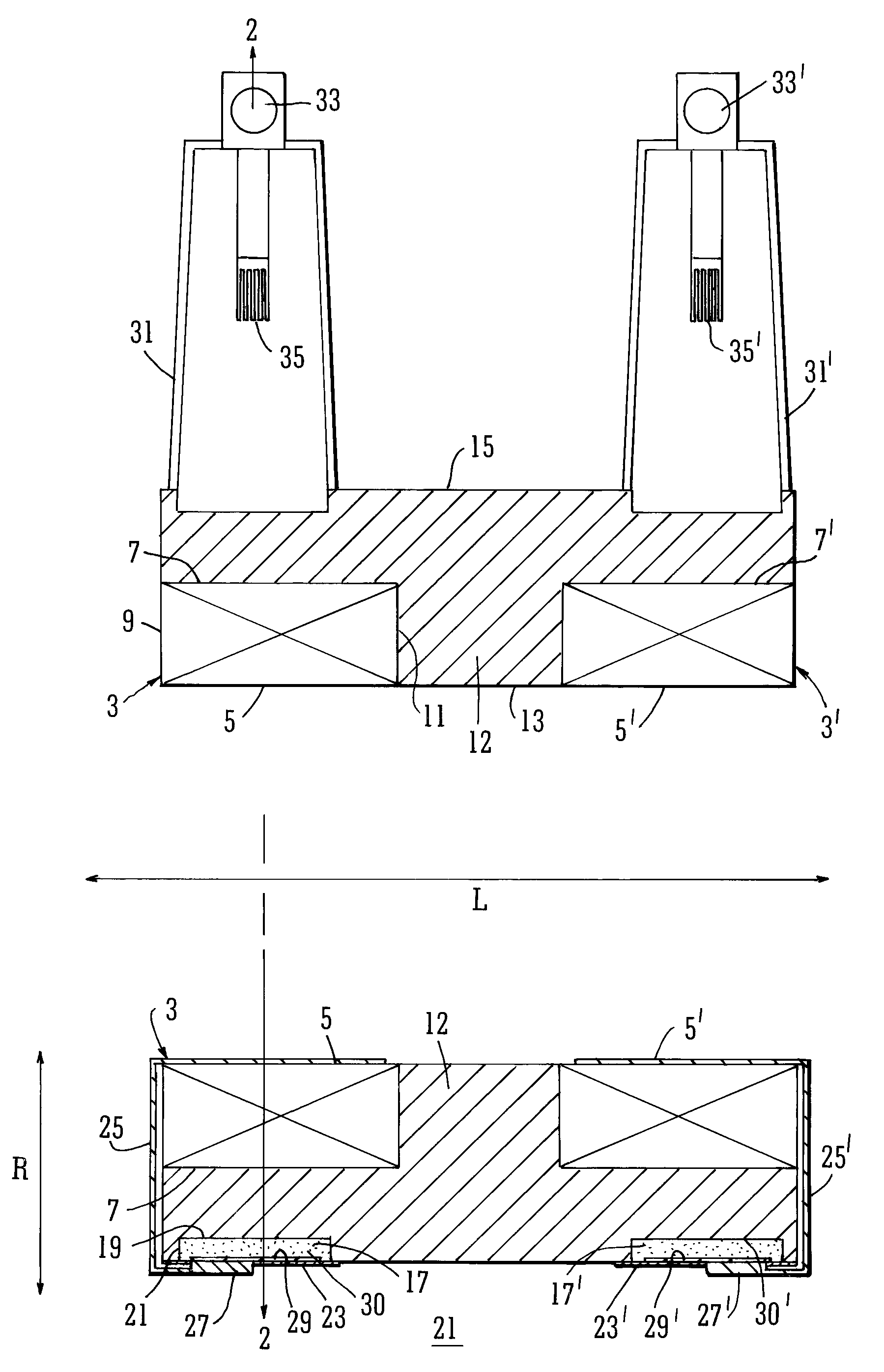
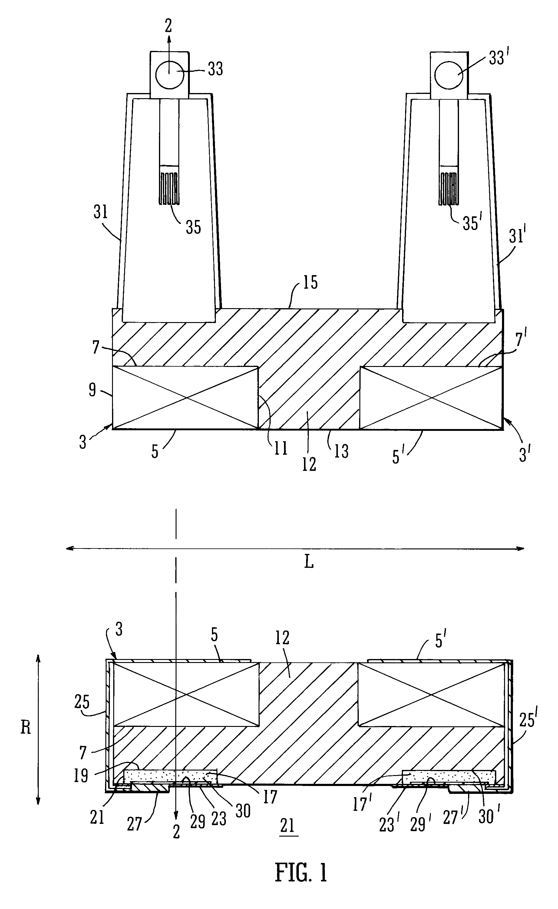
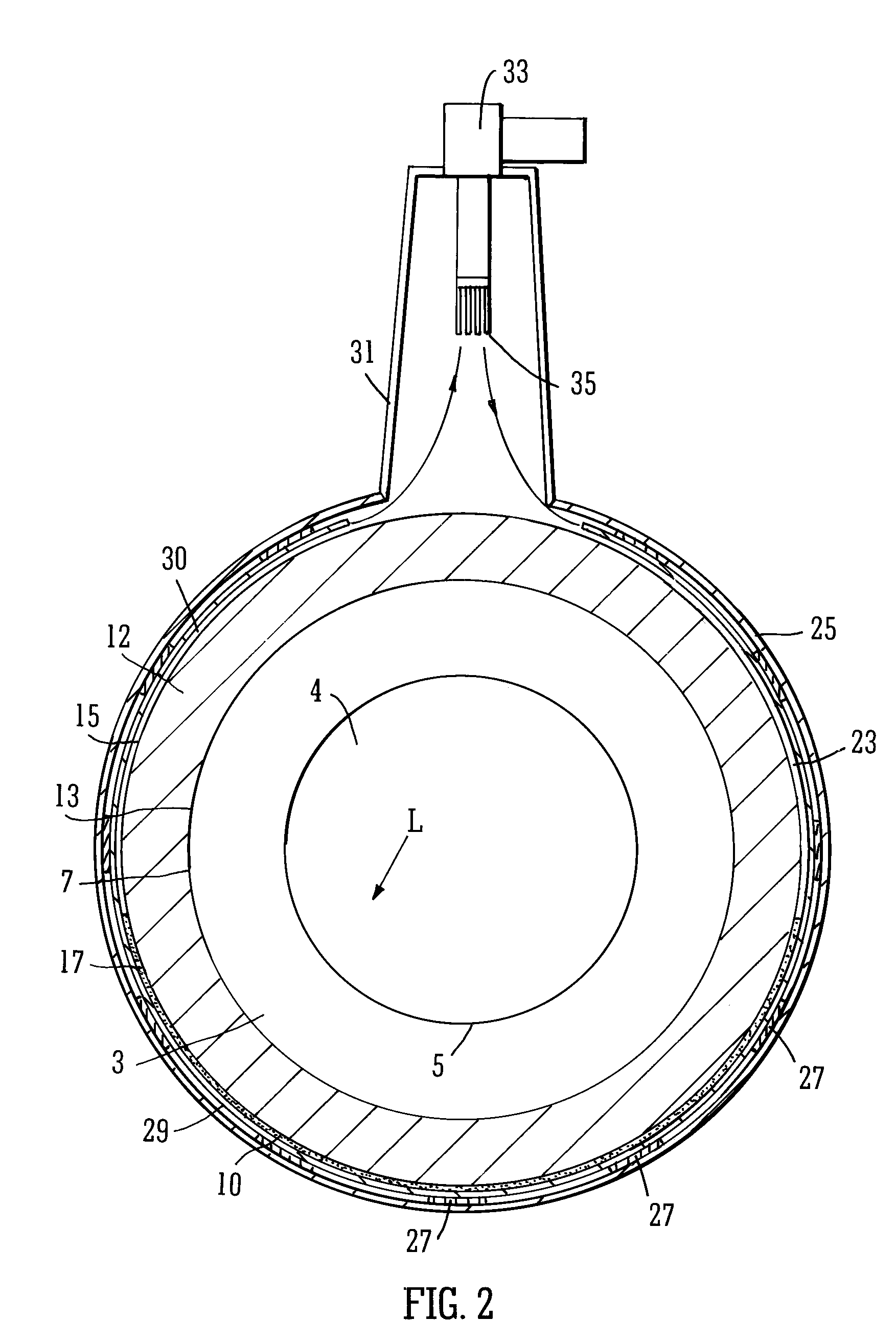
[0017]at least one superconducting coil, and

[0018]a cryogen chamber which is situated local to the superconducting coil for containing cryogen in use;

[0019]wherein the system further comprises thermally conductive means arranged to facilitate heat transfer from the at least one superconducting coil to the cryogen chamber to vaporize cryogen contained therein in use and thereby remove heat from the at least one coil, the thermally conductive means being highly thermally conductive at cryogenic temperatures;

[0020]and wherein the cryogen chamber is in fluid communication with a cryogen recondensing unit, whereby vaporized cryogen may flow from the cryogen chamber to the cryogen recondensing unit to be recondensed in use before returning to the cryogen chamb...


PUM


Abstract

A superconducting system comprises a superconducting coil (3) mounted in a support (12). The coil is surrounded by a cryogen chamber (17) which is located radially outwardly from the coil (3) on the other side of the support (12). The cryogen chamber is in fluid communication with a cryogen recondensing unit (33) whereby vaporized cryogen may flow from the cryogen chamber (17) to the cryogen recondensing unit (33) to be recondensed in use before returning to the cryogen chamber. Thermally conductive means (25) is arranged to facilitate heat transfer from the superconducting coil (3) to the cryogen chamber (17) to vaporize cryogen contained therein in use and thereby remove heat from the coil. The thermally conductive means (25) is highly thermally conductive at cryogenic temperatures. In use, the highly thermally conductive means (25) facilitates transfer of heat from the coil (3) to the interior of the cryogen chamber (17) to vaporize cryogen located therein. A thermal conduction path is therefore used to transfer heat from the coil to the cryogen in the cryogen chamber. Cryogen vaporized in the cryogen chamber then flows to the cryogen recondensing unit (33) to be recondensed before returning to the chamber, while the vaporized cryogen acts as the heat transfer medium over the longer distance between the cryogen chamber and the recondensing unit.

Description

BACKGROUND[0001]1. Field of the Invention[0002]The present invention relates to superconducting systems, and more particularly to cooling systems and methods for a superconducting system including one or more superconducting coils.[0003]2. Description of the Related Art[0004]Superconducting systems are used in many applications, including, for example, rotors, magnetic energy storage devices, generators, motors, and magnetic systems, e.g. magnetic resonance imaging (MRI), or systems for use in particle physics applications, such as particle accelerators. The present invention is particularly, although not exclusively, directed to a superconducting magnet system.[0005]Various methods for cooling coils of superconducting systems have been proposed. Some conventional cooling methods for superconducting coils involve immersing the coil in a liquid cryogenic coolant or “cryogen.” The cryogen most commonly used is liquid helium. The cryogen absorbs heat from the superconductor, and is vap...

Claims


Application Information

Patent Timeline
IPC IPC(8): F17C5/02
CPCH01F6/04H01F27/2876H01F27/22H01F6/06F17C13/007G01R33/3815
Inventor BEGG, MICHAEL COLINGOLDIE, FREDERICK THOMAS DAVID
Owner TESLA ENG
Why Eureka
Try Eureka