Insulated tank assembly with insulation stop and method of assembly thereof

a technology of insulating tank and stop, which is applied in the direction of packaging foodstuffs, domestic cooling devices, packaged goods, etc., can solve the problems of flammability or easy damage of many polymer foams used for insulation purposes, and the prior art has not been able to stop rolling, and achieves the effect of easing the passage of the outer shell

Inactive Publication Date: 2009-02-12
OWENS CORNING INTELLECTUAL CAPITAL LLC
View PDF13 Cites 13 Cited by
  • Summary
  • Abstract
  • Description
  • Claims
  • Application Information

AI Technical Summary

Benefits of technology

[0018]In such stretching and positioning maneuvers, a construction of the sealing strip whereby the strip length is less than either the continuous outer top edge length or the continuous outer bottom edge length, or ideally both, may be desirable. Any construction where the strip length is less than both of the continuous outer top edge length and the continuous outer bottom edge length, will have an intrinsically elastic nature, given at least a slightly elastic material substrate. For example, in an illustrated embodiment in which the seal strip has “V” shaped dentate portions, stretching the strip will cause the open v-like notches of the dentate portions to open slightly, and thereby to elongate the overall strip. In other illustrated embodiments, the same effect may be observed with serpentine-type constructions and others.
[0019]The construction in which the strip length is less than either the continuous outer top edge length or the continuous outer bottom edge length, also has advantages. Sliding the outer shell over the inner tank while compressing the sealing strip between the inner tank and the outer shell causes frictional interactions between the sealing strip and the walls of the inner tank and the outer shell that can cause the sealing strip to roll or otherwise be displaced from its intended position. A sealing device according to the instant invention has a resistance to rolling compared to the planar, ring-like constructions seen in the prior art. This is due to the fact that a strip in which the strip length is less than either the continuous outer top edge length or the continuous outer bottom edge length is necessarily non-planar, that is, that all points on at least one of these edges do not lie on a single plane. In particular, it has been seen that the “dentate” construction as illustrated in a preferred embodiment is particularly resistant to rolling.
[0020]To assist in keeping the sealing strip in its predetermined position, the sealing strip may be affixed to the inner tank by adhesive before the shell is slid onto the tank. Additionally or alternatively, in other embodiments, the at least one annular clearance space may include one or more abutment members providing a positioning stop for the sealing device. A chamfer may be present along an edge selected from the edges consisting of the outer top edge and the outer bottom edge of the sealing strip in order to ease the passage of the outer shell over the inner tank.

Problems solved by technology

A number of issues arise with such construction techniques.
Secondly, tanks may have a number of inlet, outlet, and drain fittings, as well as electronic or other controls that may need to traverse the annular space.
Additionally, many polymer foams used for insulation purposes are either flammable or easily damaged by heat, and must be kept a safe distance from any heating elements.
In particular, the prior art has sought, with limited success, to control two issues related to insulation stops for insulated tank assemblies.
The first involves a mechanical issue related to the insulation stop itself.
Sliding the shell into place can cause the stop to roll, sometimes irregularly, as the frictional forces resulting from the compression of the stop act on the surface of the stop.

Method used


Image

  • Insulated tank assembly with insulation stop and method of assembly thereof
  • Insulated tank assembly with insulation stop and method of assembly thereof
  • Insulated tank assembly with insulation stop and method of assembly thereof

Examples


Embodiment Construction

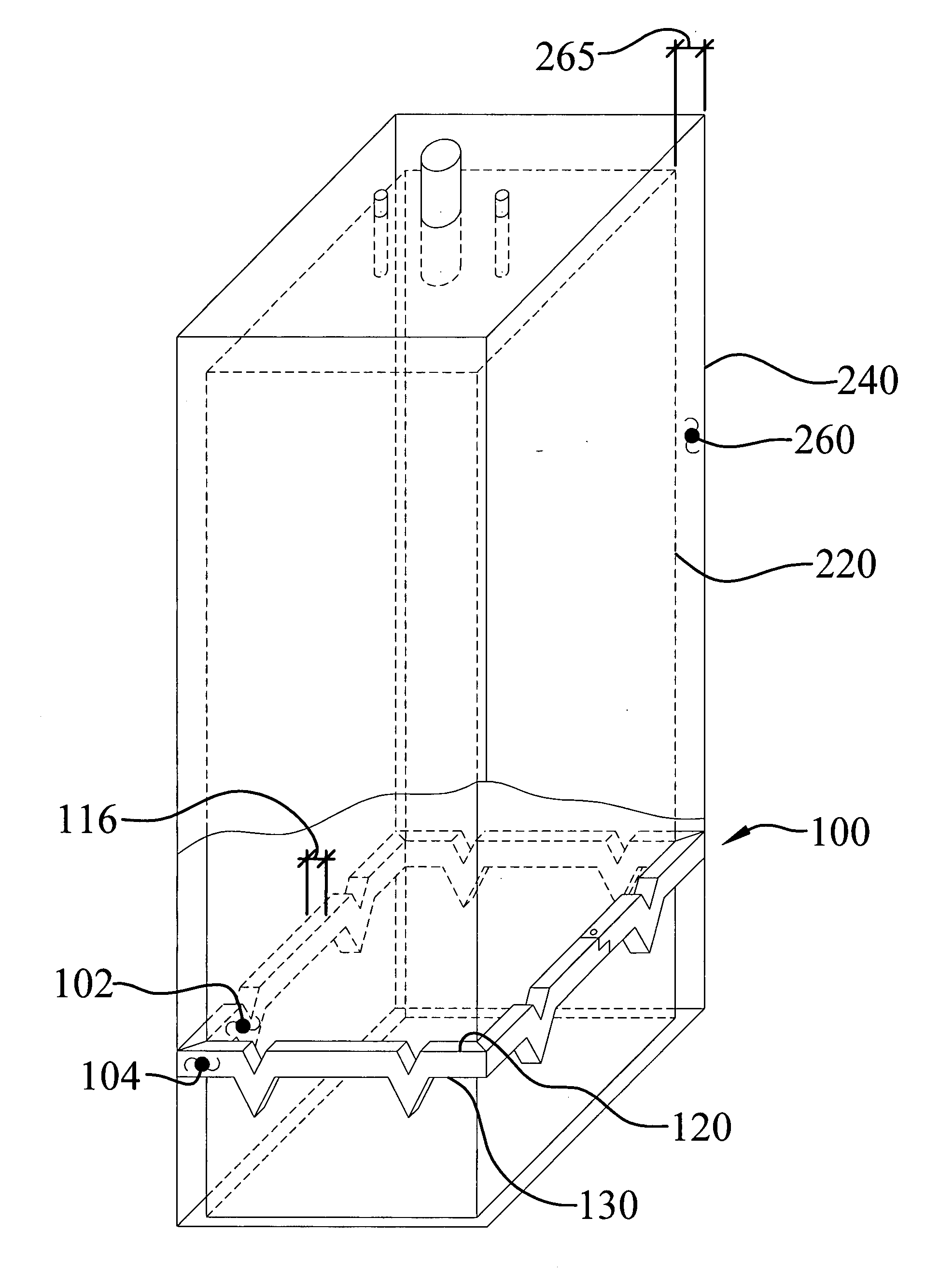
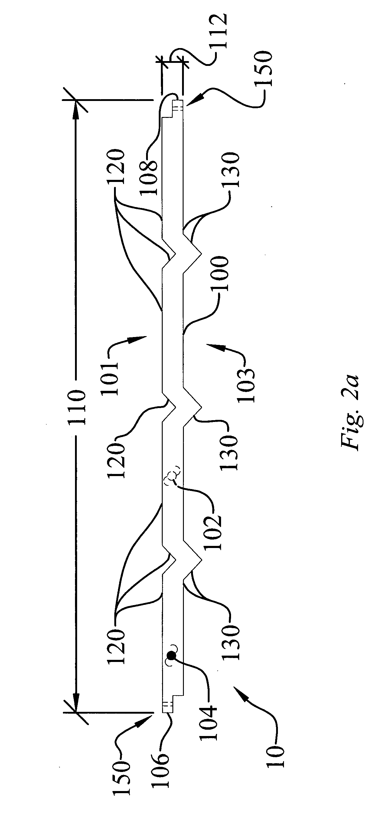
[0044]The insulated tank assembly with insulation stop and method of assembly of the instant invention enables a significant advance in the state of the art. The preferred embodiments of the device accomplish this by new and novel arrangements of elements and methods that are configured in unique and novel ways and which demonstrate previously unavailable but preferred and desirable capabilities. The detailed description set forth below in connection with the drawings is intended merely as a description of the presently preferred embodiments of the invention, and is not intended to represent the only form in which the present invention may be constructed or utilized. The description sets forth the designs, functions, means, and methods of implementing the invention in connection with the illustrated embodiments. It is to be understood, however, that the same or equivalent functions and features may be accomplished by different embodiments that are also intended to be encompassed wit...


PUM

PropertyMeasurementUnit
densityaaaaaaaaaa
densityaaaaaaaaaa
thicknessaaaaaaaaaa

Abstract

An insulated tank assembly with insulation stop and a method of constructing such an assembly. The assembly includes an inner tank with an outer shell located in spaced relation to and surrounding the inner tank, creating at least one annular clearance space between the tank and the shell. The space is closed by a sealing device that includes a circumferential sealing strip having an unstretched strip length that is less than either the continuous outer top edge length or the continuous outer bottom edge length, or both, of the strip. Such length relationships make the sealing strip both resilient and resistant to rolling during construction of the assembly. The sealing strip may be a fibrous strip. The tank assembly may be insulated by placing insulating material within the at least one annular clearance space, which may be a foamable insulation material, foamed in place within the annular clearance space.

Description

TECHNICAL FIELD AND INDUSTRIAL APPLICABILITY OF THE INVENTION[0001]The invention relates to the field of insulated tank assemblies, and in particular to an assembly utilizing an improved insulation stop for the retention of foam insulation within such an assembly.BACKGROUND OF THE INVENTION[0002]Insulated tank assemblies, such as water heaters and other devices, have long been known in the art. The term “tank” is used in its broadest sense in this disclosure, to define any container having a volume, and therefore, one skilled in the art will realize that the assembly, components, and methods described herein are equally applicable to other tank assemblies such as dish washers, refrigerators, storage tanks, and innumerable other insulated containers.[0003]Such assemblies typically comprise an inner storage tank or vessel and an outer shell or jacket. Typically, but not exclusively, the inner storage tank and outer shell are cylindrical, with the outer shell disposed concentrically ov...

Claims


Application Information

Patent Timeline
Patent Type & Authority Applications(United States)
IPC IPC(8): B65D90/04B23P19/00B65D8/18B65D81/38
CPCB65D88/748Y10T29/53F24H1/182B65D90/06
Inventor ROCKWELL, ANTHONY L.SCHECHTER, CHRISTOPHER B.CAMPEN, SCOTT A.
Owner OWENS CORNING INTELLECTUAL CAPITAL LLC
Why Eureka
Try Eureka