Active vibration isolating support apparatus and method for controlling the same
a technology of active vibration and support apparatus, which is applied in the direction of shock absorbers, jet propulsion mountings, instruments, etc., can solve the problems of too slow to effectively reduce temporary vibration and inability to reduce transient vibration, and achieve the effect of reducing transient vibration
- Summary
- Abstract
- Description
- Claims
- Application Information
AI Technical Summary
Benefits of technology
Problems solved by technology
Method used
Image
Examples
first embodiment
[0054]First, an active vibration isolating support apparatus according to the first embodiment of the present invention will be explained.
[0055](Whole Structure of the Active Vibration Isolating Support Apparatus)
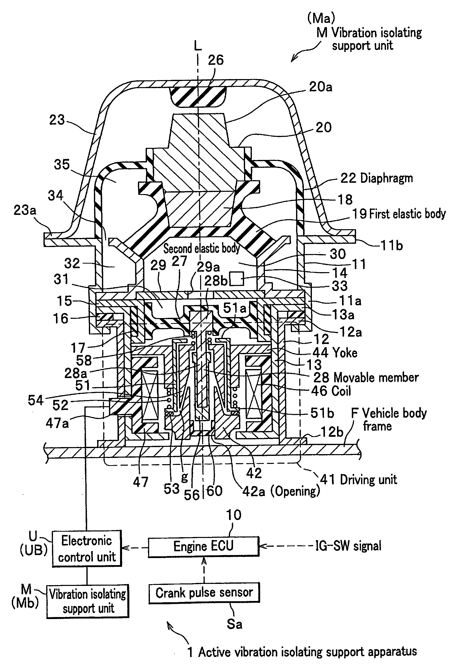
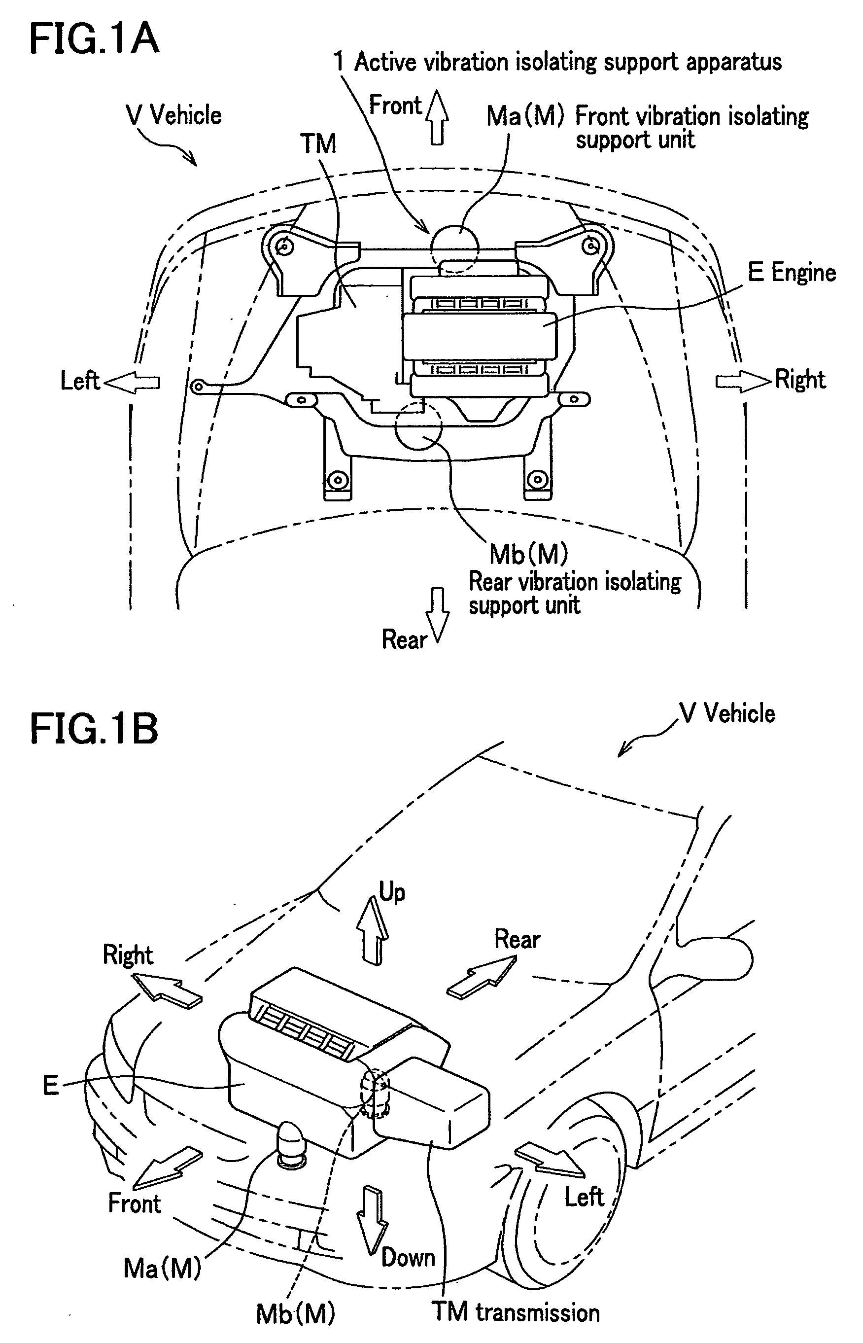
[0056]In FIG. 1A and FIG. 1B, an active vibration isolating support apparatus 1 according to the present invention can be driven to extend and contract in a vertical direction, and includes two engine mounts (active control mounts) M which are used to elastically support an engine E of a vehicle V in a vehicle body frame, and are disposed ahead of and behind the engine E. Hereinafter, an “engine mount” is referred to as a “vibration isolating support unit”.
[0057]Here, the engine E is a so-called side-ways mounted transversal V engine with six-cylinders in which one end of a crankshaft (not shown) is connected to a transmission TM, and the crankshaft is disposed in a direction transverse to a body of the vehicle V. Therefore, the engine E is disposed in a direction so that t...
second embodiment
[0154]Next, an active vibration isolating support apparatus according to the second embodiment of the present invention will be explained.
[0155]FIGS. 10-15 show the second embodiment of the present invention. FIG. 10 is a longitudinal sectional view showing the structure of an active control mount of the active vibration isolating support apparatus according to the second embodiment; FIG. 11 is a partial enlarged view of unit 2 of FIG. 10; FIG. 12 shows the supporting state of an engine by a vibration isolating support unit of the active vibration isolating support apparatus; FIG. 13 is a longitudinal sectional view of a cylinder of the engine; FIG. 14 is a flowchart representing a control flow of a driving unit during normal operation; and FIG. 15 is an explanatory diagram of step 35 in the flowchart in FIG. 14.
[0156]As shown in FIG. 10 and FIG. 11, the active control mount M′ (hereinafter, referred as a “vibration isolating support unit M′”) of the active vibration isolating suppo...
third embodiment
[0200]Next, a third embodiment according to the present invention will be explained.
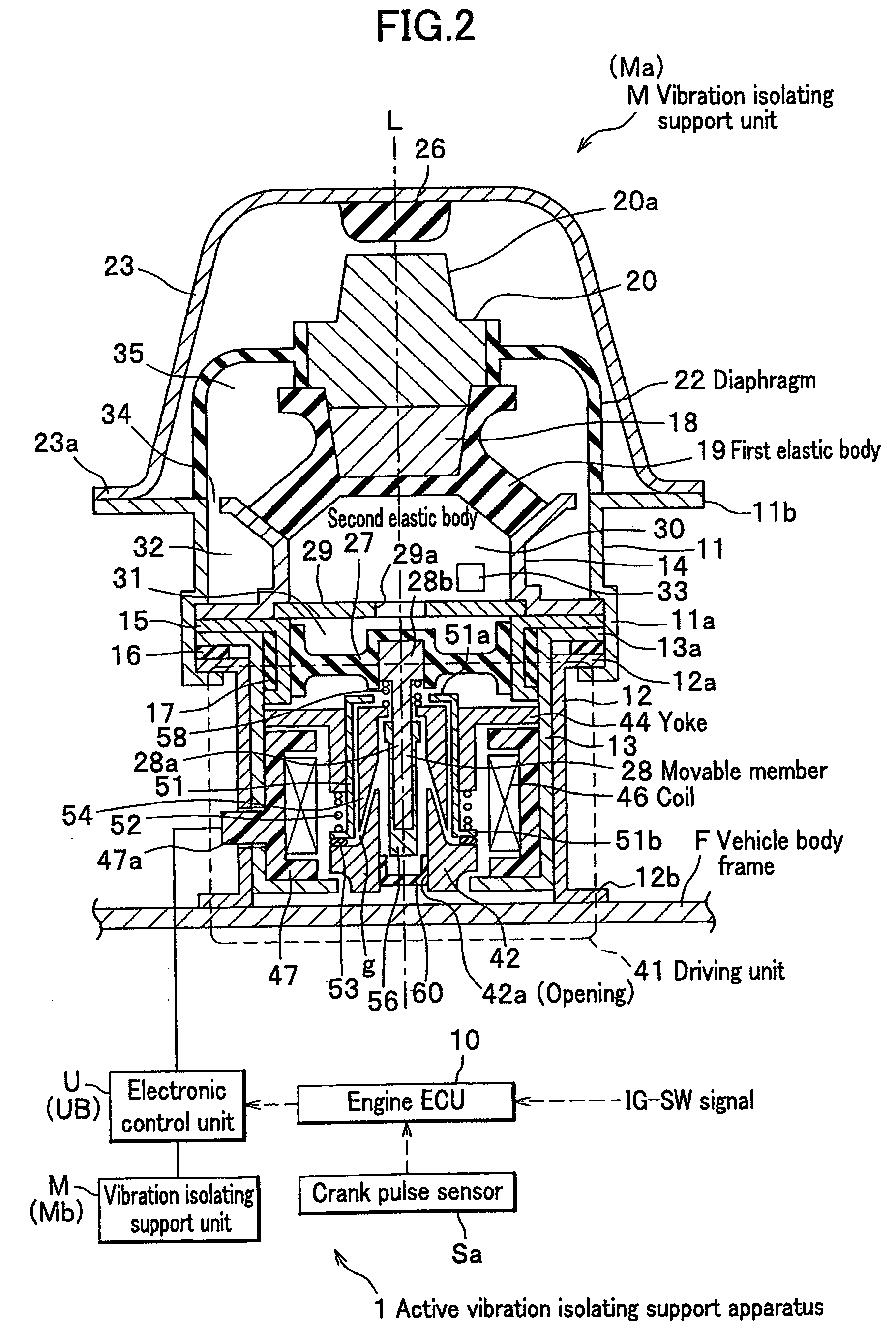
[0201]A feature of the active vibration isolating support apparatus 1 of the present embodiment is basically identical to that of the first embodiment. An arrangement of the vibration isolating support unit M of the active vibration isolating support apparatus 1 according to the present embodiment is identical to those shown in FIG. 1A and FIG. 1B. The feature of the active vibration isolating support apparatus 1 includes an active control mount electronic control unit UB (hereinafter, referred to as electronic control unit UB as shown in FIG. 2 and FIG. 3) which controls the vibration isolating support unit M shown in FIG. 2. In addition, hardware of the electronic control unit UB and connections of the electronic control unit UB with the engine ECU are identical to those of the first embodiment as shown in FIG. 3.
[0202]For reference's sake, the electronic control unit UB includes a storage unit 165...
PUM
 Abstract
Description
Claims
Application Information
 - R&D
- Intellectual Property
- Life Sciences
- Materials
- Tech Scout
- Unparalleled Data Quality
- Higher Quality Content
- 60% Fewer Hallucinations
Browse by: Latest US Patents, China's latest patents, Technical Efficacy Thesaurus, Application Domain, Technology Topic, Popular Technical Reports.
© 2025 PatSnap. All rights reserved.Legal|Privacy policy|Modern Slavery Act Transparency Statement|Sitemap|About US| Contact US: help@patsnap.com


