Antenna structure and radio communication device using the same

a radio communication device and antenna structure technology, applied in the structure of resonant antennas, elongated active elements, radiating elements, etc., can solve the problems of difficult shared use of surface mount antennas b>30/b>, deterioration of antenna characteristics, etc., to facilitate shared facilitate the effect of sharing use of surface mount antennas and cost reduction

Inactive Publication Date: 2009-02-12
MURATA MFG CO LTD +1
View PDF10 Cites 24 Cited by
  • Summary
  • Abstract
  • Description
  • Claims
  • Application Information

AI Technical Summary

Benefits of technology

[0022]On the other hand, in an antenna structure according to the present disclosure, a feeding electrode is disposed on a board on which a surface mount antenna is mounted, and the feeding electrode is not disposed on the substrate of the surface mount antenna. Thus, according to the present disclosure, when the model of the radio communication device is changed, it is only necessary to change the relative position of the feeding electrode on the board and no change in the design of the surface mount antenna is necessary. That is, in the antenna structure, the surface mount antenna can serve as a surface mount antenna common to a plurality of models of radio communication devices, and thus shared use of the surface mount antenna can be facilitated.
[0023]In addition, a resonant frequency of the radiation electrode can be adjusted or changed without a design change of the surface mount antenna, because of a configuration in which at least one reactance portion for adjusting the resonant frequency of the radiation electrode is provided on the board. For example, a capacitance or an inductance can be connected between ground and either end or both ends of the surface mount antenna. Thus, the configuration in which a reactance portion for adjusting the resonant frequency of the radiation electrode is provided on the board further facilitates shared use of the surface mount antenna.
[0024]In addition, the surface mount antenna is allowed to perform radio communication in a plurality of different frequency bands, by a configuration in which the radiation electrode has a plurality of antenna resonant modes with different resonant frequencies. This permits radio communication in a plurality of frequency bands without providing a plurality of antennas in a radio communication device. Therefore, a radio communication device provided with an antenna structure having a plurality of antenna resonant modes permits downsizing and cost reduction, as compared to the case where it is necessary to provide a plurality of antennas in the radio communication device.
[0025]In addition, with a configuration in which the feeding electrode is also operable as an antenna, not only the radiation electrode but also the feeding electrode can operate as an antenna. That is, the antenna structure according to the present disclosure in which the feeding electrode is also operable as an antenna permits radio communication in a plurality of different frequency bands, and thus multi-functionality of an antenna structure can be achieved. Accordingly, with the antenna structure of the present disclosure, downsizing and cost reduction of a radio communication device can be achieved.

Problems solved by technology

Thus, shared use of the surface mount antenna 30 is difficult.
However, with the surface mount antenna 40, the following problems are likely to occur.
The stray capacitance Cb adversely affects the resonant frequency of the radiation electrode 42, which leads to a problem of deterioration of antenna characteristics.

Method used


Image

  • Antenna structure and radio communication device using the same
  • Antenna structure and radio communication device using the same
  • Antenna structure and radio communication device using the same

Examples


first embodiment

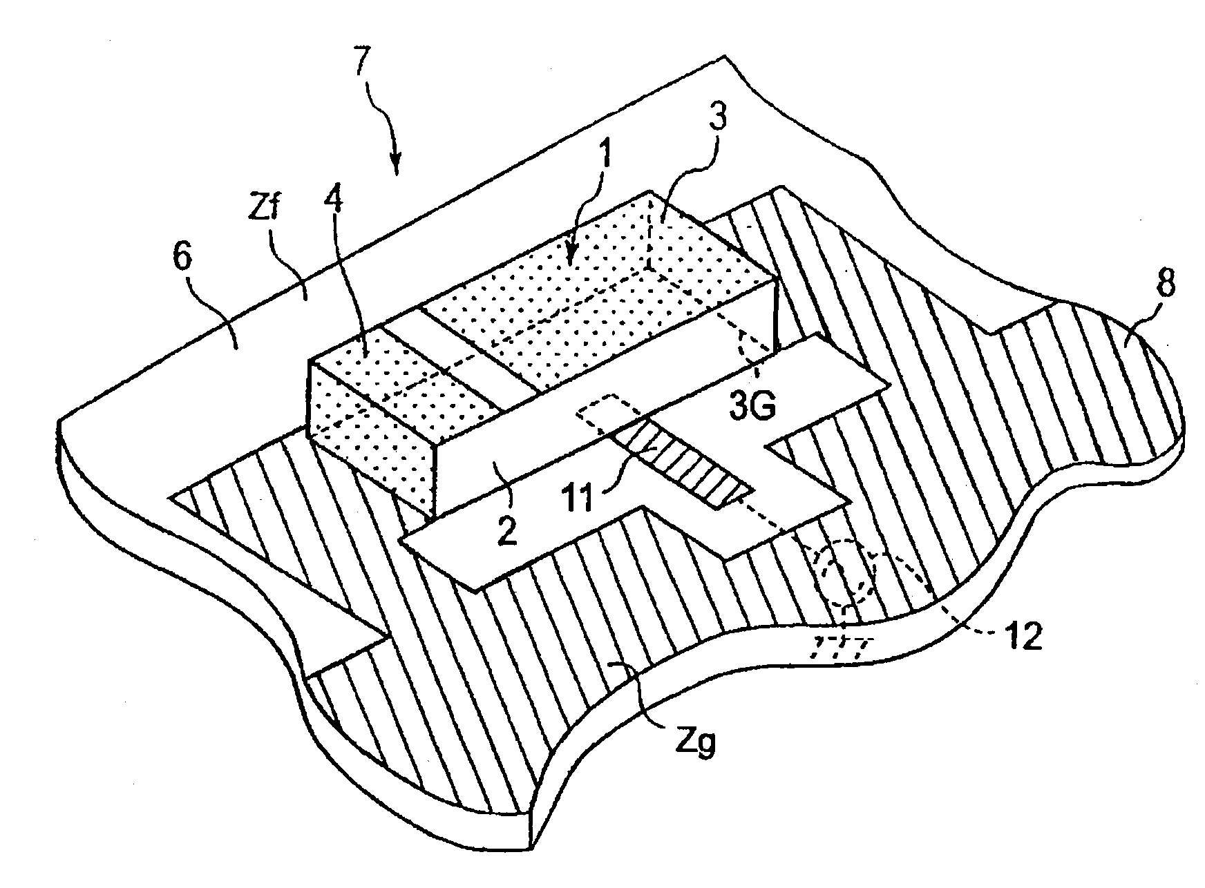
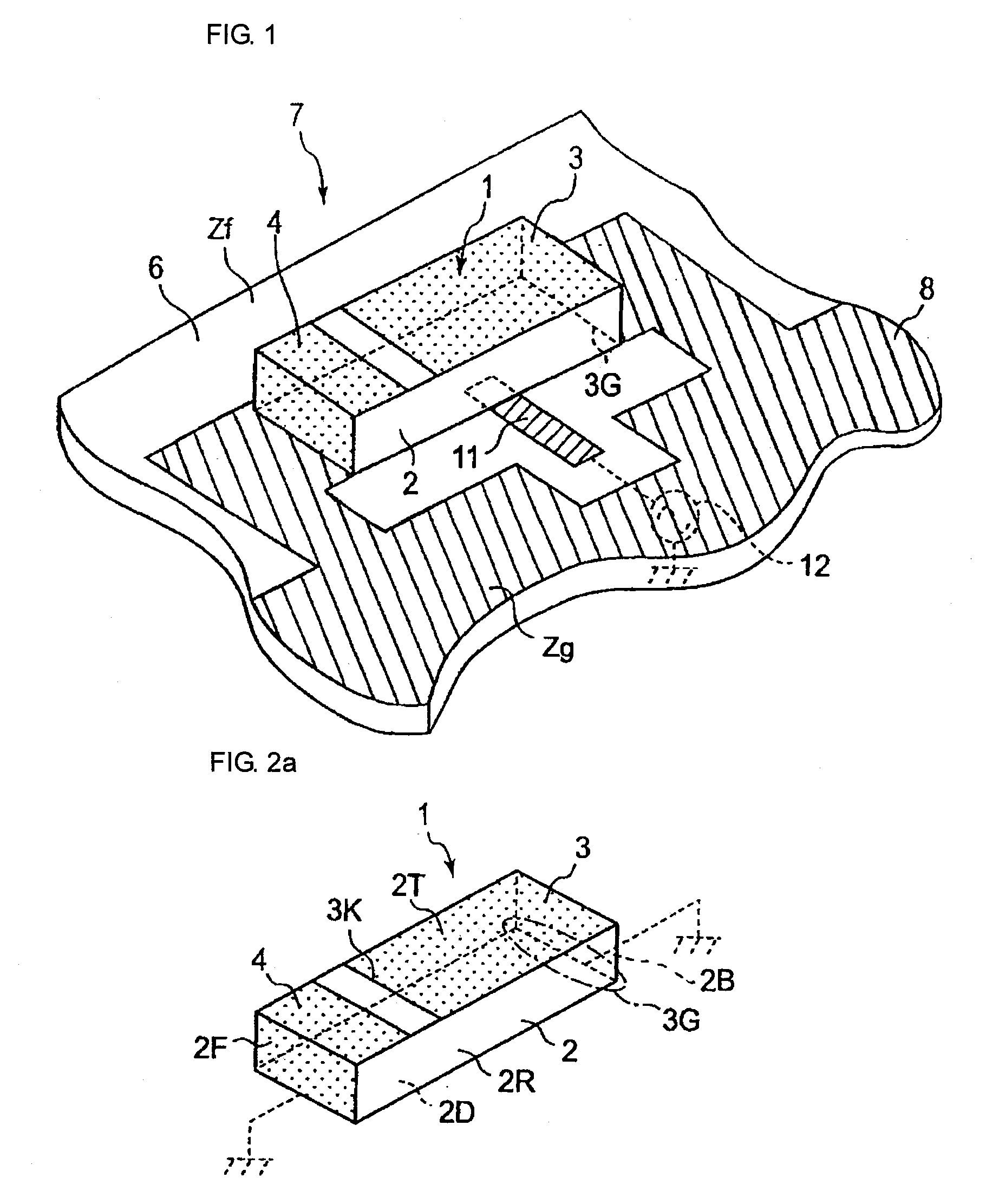
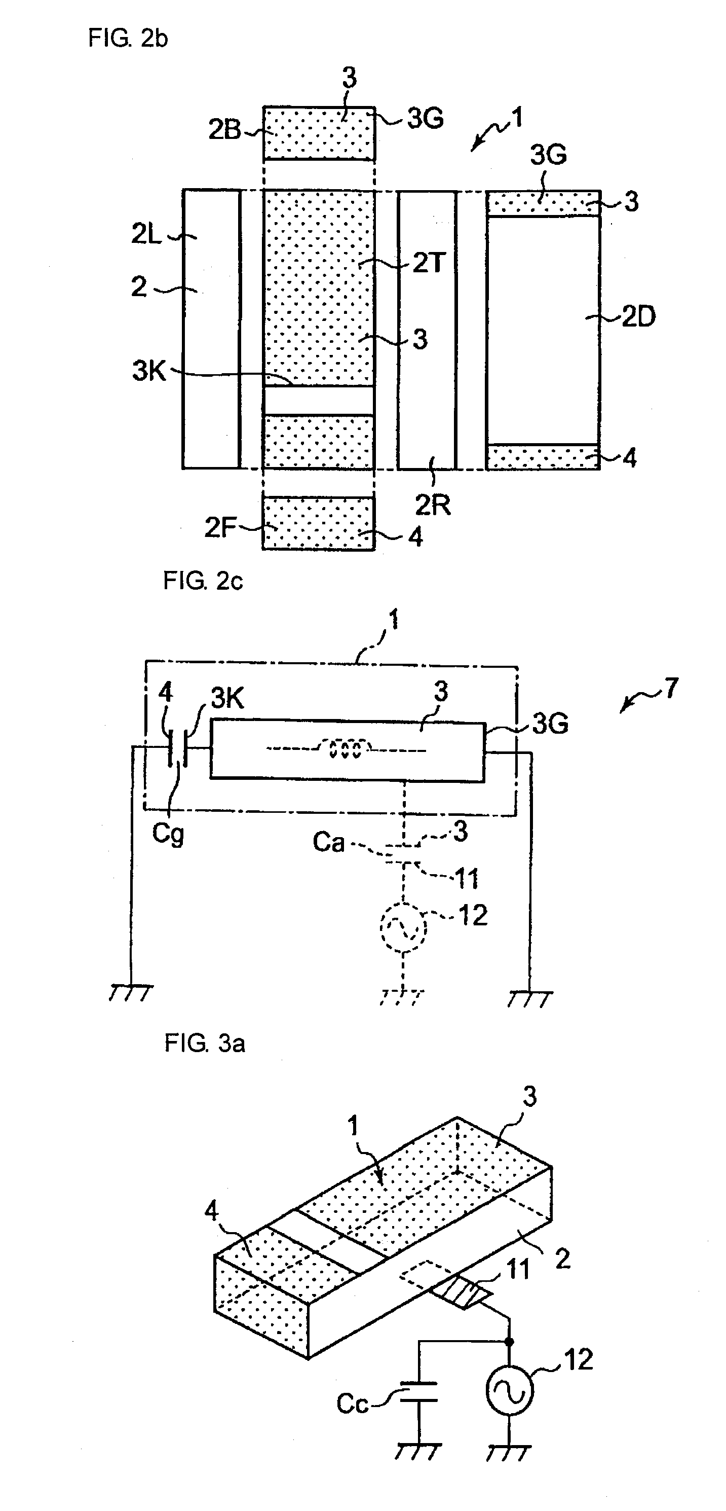
[0059]In the first embodiment, the surface mount antenna 1 is configured as described above. In addition, the surface mount antenna 1 has an equivalent circuit illustrated by solid lines in FIG. 2c. Thus, the resonant frequency of the radiation electrode 3 is mainly determined in relation to an inductance value of the radiation electrode 3 and a capacitance Cg between the open end 3K of the radiation electrode 3 and the ground connection electrode 4. With this arrangement, the surface mount antenna 1 is designed such that the radiation electrode 3 can have a predetermined resonant frequency. Specifically, in the design of the surface mount antenna 1, the physical length from the ground connection portion 3G to the open end 3K of the radiation electrode 3 which relates to the inductance value of the radiation electrode 3, the capacitance Cg between the open end 3K of the radiation electrode 3 and the ground connection electrode 4, and so forth, are associated with each other while th...

second embodiment

[0071]In this second embodiment, a radiation electrode 3 has a plurality of antenna resonant modes with different resonant frequencies. An antenna structure 7 (not shown) is capable of radio communication in a plurality of different frequency bands. Various configurations may be possible to provide a plurality of antenna resonant modes to the radiation electrode 3, and any of such configurations may be employed. Examples of such configurations include a configuration illustrated in FIG. 5a and a configuration illustrated in FIG. 5b, for example.

[0072]In the example of FIG. 5a, the radiation electrode 3 is branched into plural portions (two, in the example of FIG. 5a) at a section between a ground connection portion 3G to an open-end 3K. In the radiation electrode 3, a plurality of branched radiation electrodes 15a and 15b are formed. In other words, a slit 20 extending from the open end 3K of the radiation electrode 3 toward the ground connection portion 3G is provided on the radiat...


PUM


Abstract

A radiation electrode is formed on a substrate of a surface mount antenna. One end of the radiation electrode forms a ground connection portion connected to ground, and the other end of the radiation electrode forms an open end. A ground connection electrode for connecting the open end of the radiation electrode to ground via a capacitance is provided on the substrate. No feeding electrode for feeding power to the radiation electrode is provided on the substrate. This surface mount antenna is mounted on a non-ground region (a region on which a ground electrode is not formed) of a board so as to constitute an antenna structure. On the board of the antenna structure, a feeding electrode for capacitively feeding power to the radiation electrode is provided at a position between the ground connection portion and the open end.

Description

CROSS-REFERENCE TO RELATED APPLICATIONS[0001]This is a continuation under 35 U.S.C. §111(a) of PCT / JP2007 / 066196 filed Aug. 21, 2007, and claims priority of JP2006-254565 filed Sep. 20, 2006, and JP2007-053077, filed Mar. 2, 2007, incorporated by reference.BACKGROUND[0002]1. Technical Field[0003]The present disclosure relates to an antenna structure for use in a radio communication device such as a mobile phone and to a radio communication device using the antenna structure.[0004]2. Background Art[0005]FIG. 8 illustrates an example of a configuration of a conventional surface mount antenna by a schematic perspective view (for example, see Patent Document 1). This surface mount antenna 30 has a dielectric substrate 31. A radiation electrode 32 is formed on the dielectric substrate 31. In addition, a feeding electrode 33 and a ground connection electrode 34 are formed on the dielectric substrate 31. The radiation electrode 32 has a predetermined resonant frequency to perform antenna o...

Claims


Application Information

Patent Timeline
Patent Type & Authority Applications(United States)
IPC IPC(8): H01Q1/24H01Q1/38
CPCH01Q1/2283H01Q9/30H01Q9/0457H01Q9/0421
Inventor TSUBAKI, NOBUHITOISHIZUKA, KENICHIKAWAHATA, KAZUNARI
Owner MURATA MFG CO LTD
Why Eureka
Try Eureka