Acoustic wave induced light emitting golf ball

a golf ball and acoustic wave technology, applied in the field of acoustic wave induced light-emitting golf balls, can solve the problems of inability to work in specific hitting directions, easy damage to products, and stillness of conventional light-emitting golf balls, and achieve the effect of prolonging product life and low defective ra

Inactive Publication Date: 2009-02-12
HUANG CHANG HSIU +1
View PDF4 Cites 43 Cited by
  • Summary
  • Abstract
  • Description
  • Claims
  • Application Information

AI Technical Summary

Benefits of technology

[0010]The next object of the present invention is to provide an acoustic wave induced light emitting golf ball. It has an extremely low defective rate...

Problems solved by technology

However, the conventional light emitting golf ball still has the following disadvantages.
[1] Some specific hitting directions cannot work.
The product is easy to be damaged during the high temperature injection process.
Thus, the spring ...

Method used


Image

  • Acoustic wave induced light emitting golf ball
  • Acoustic wave induced light emitting golf ball
  • Acoustic wave induced light emitting golf ball

Examples


Embodiment Construction

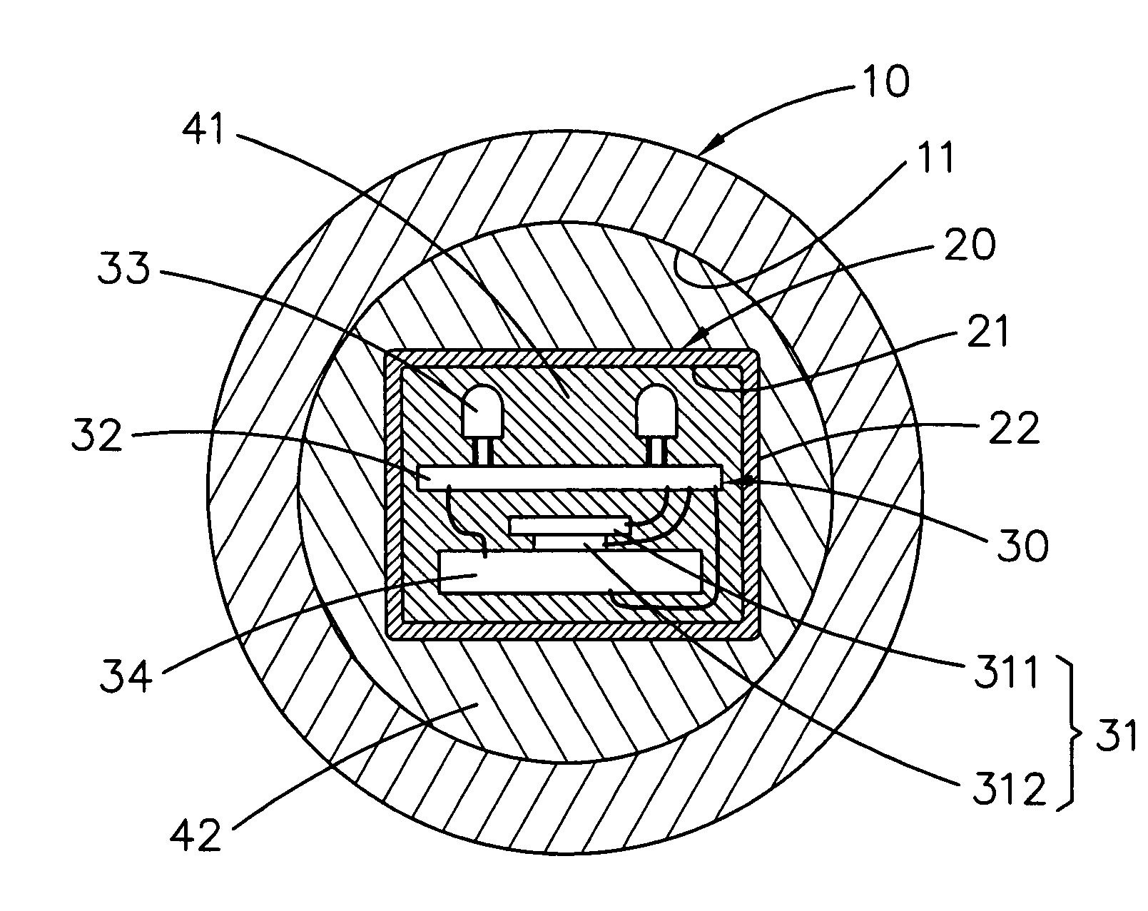
[0022]Referring to FIG. 7, the present invention is an acoustic wave induced light emitting golf ball. It comprises:

[0023]a spherical housing 10 having an internal space 11;

[0024]a fixing container 20 having an inner surface 21 and an outer surface 22, the fixing container 20 being disposed in the internal space 11 and being light transmittable;

[0025]a light emitting device 30 disposed in the fixing container 20, the light emitting device 30 including an acoustic wave sensor 31, a controller 32, at least one light emitting element 33, and an electricity supplier 34 (such as a small battery); when the acoustic wave sensor 31 receiving an external acoustic wave signal higher than a predetermined value (for example, while hitting the spherical housing 10 and then generating an acoustic wave signal as shown in FIG. 9), the acoustic wave sensor 31 sending out an activating signal to the controller 32 so that at least one light emitting element 33 emits light;

[0026]a first fitting portion...


PUM


Abstract

A light emitting golf ball is provided that includes a spherical housing, a fixing container, a light emitting device, a first fitting portion, and a second fitting portion. The light emitting device is disposed in the fixing container and includes an acoustic wave sensor, a controller, one or more light emitting elements and an electricity supplier. When the acoustic wave sensor receives an external acoustic wave signal higher than a predetermined value, it sends out an activating signal to the controller so that at least one light emitting element emits light. This invention is irrelevant to the hitting direction. It has an extremely low defective rate. Furthermore, the product life can be prolonged.

Description

BACKGROUND OF INVENTION[0001]1. Field of the Invention[0002]The present invention relates to an acoustic wave induced light emitting golf ball. More particularly, it relates to an acoustic wave induced light emitting golf ball having an acoustic wave sensor. This invention is irrelevant to the hitting direction. It has an extremely low defective rate. Furthermore, the product life can be prolonged.[0003]2. Description of the Prior Art[0004]As shown in FIGS. 1 and 2, a light emitting device 91 is mounted in a conventional light emitting golf ball 90. This light emitting device 91 includes a metal hollow tube 92, a controller 93 (such as a circuit board) and one or more small light bulb 94 (or LED, the light emitting diode). There is a spring type vibration sensor 95 disposed inside the metal hollow tube 92.[0005]Referring to FIGS. 3 and 4, if the spring type vibration sensor95 is located along an X-axis which is perpendicular to the hitting direction (along a Z-axis shown in FIGS. 3 ...

Claims


Application Information

Patent Timeline
IPC IPC(8): A63B43/06
CPCA63B37/0003A63B37/0055A63B2220/833A63B2220/808A63B43/06
Inventor HUANG, CHANG-HSIUCHOU, WEI-LUNG
Owner HUANG CHANG HSIU
Why Eureka
Try Eureka