Insulating spacer for an injection mould

a technology of insulating spacers and injection moulds, which is applied in the field of insulating spacers, can solve the problems of high requirements regarding the accuracy of insulating rings, high cost, and high requirements for high precision manufacturing of rings, and achieves the effects of low cost, low heat conductivity, and easy machin

Inactive Publication Date: 2009-02-12
LKM HEATLOCK
View PDF2 Cites 0 Cited by
  • Summary
  • Abstract
  • Description
  • Claims
  • Application Information

AI Technical Summary

Benefits of technology

[0005]It is desirable to achieve a robust and reliable solution in accordance with the objects of the present invention and keep high standard as regards quality and functionality by providing an alternative insulating element for a mould injection system.
[0019]Machining of for instance steel is less expensive than machining of ceramic material. By using a dimension adaption element formed from a material that is easy to machine, an insulating element that can be manufactured in a cost-efficient manner is provided. The insulating element is formed from a material with low heat conductivity, such as a ceramic material. Such materials are difficult to machine resulting in high costs to reach a sufficient level of accuracy. Manufacturing of ceramic parts with high precision is considered costly. Since the dimensions can be adapted by machining the dimension adaption element, lower precision regarding the ceramic part is required compared to known insulating spacers and thus a more cost-efficient insulating element is provided.

Problems solved by technology

An issue with this arrangement is that the requirements regarding accuracy of the insulating ring are rather high in order to position the hot runner injection system correctly and / or to avoid leakage.
Thus, the ceramic rings need to be manufactured with high precision, which may be considered complex and costly.

Method used


Image

  • Insulating spacer for an injection mould
  • Insulating spacer for an injection mould
  • Insulating spacer for an injection mould

Examples


Embodiment Construction

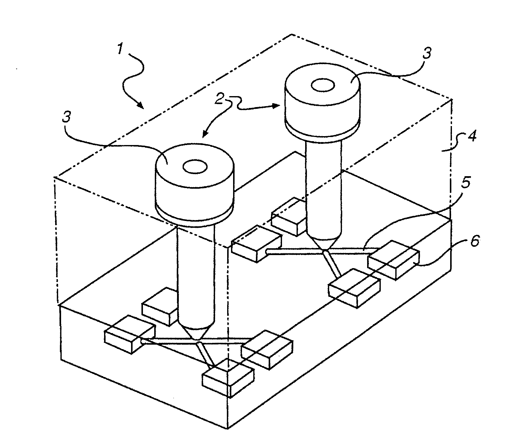
[0029]FIG. 1 shows a schematic perspective view of selected parts of an injection mould 1 comprising a hot runner injection system 2 with two heat channel tools 3 and a mould 4. In the mould 4 runners 5 are provided for distribution of the flow of material from the heat channel tools 3 to cavities 6 in the mould 4. Several cavities 6 may be provided in the mould 4 for simultaneous moulding of several pieces of goods. The injection mould 1 may have a common inlet channel (not shown).

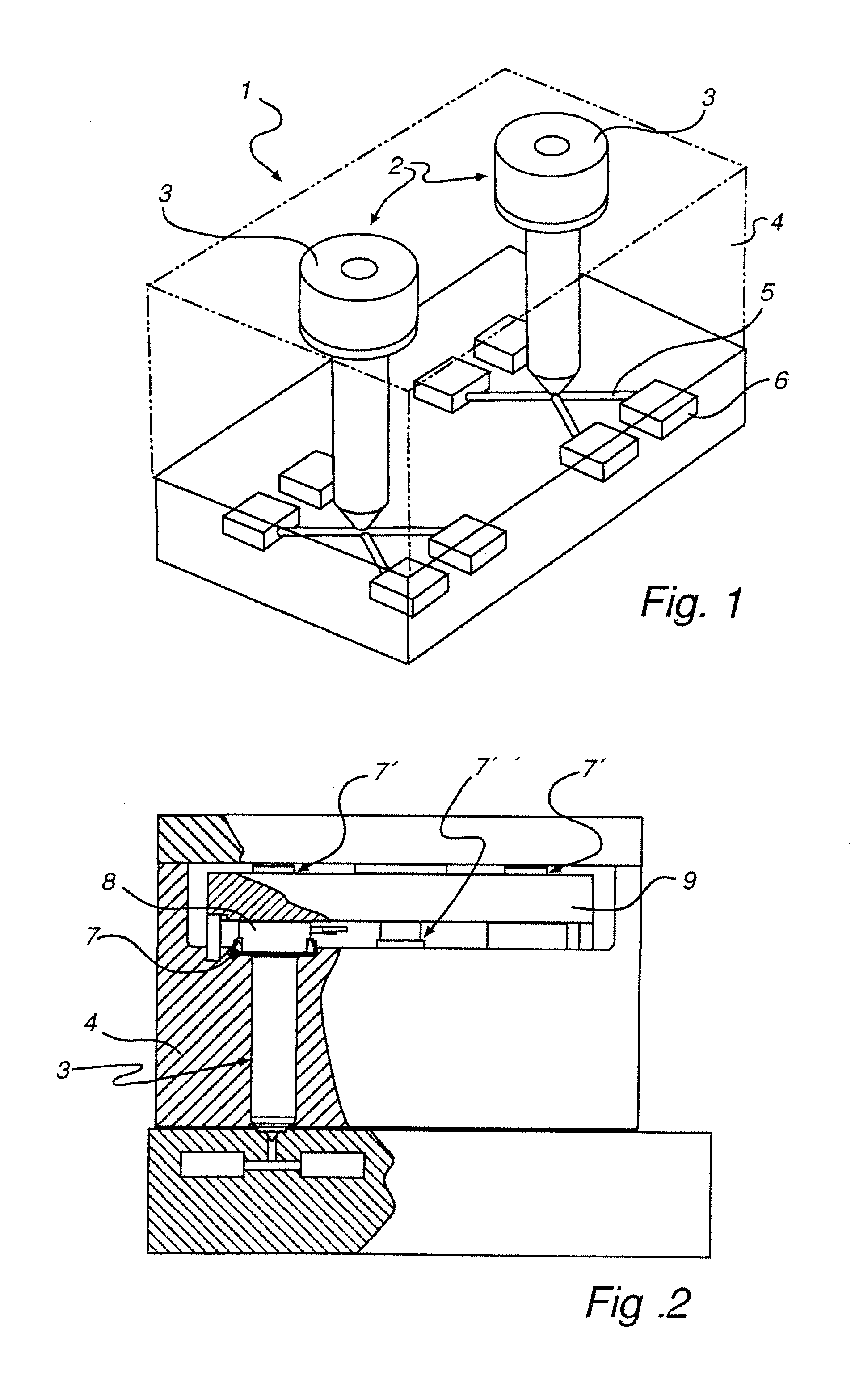
[0030]FIG. 2 shows a partial sectional view of the injection mould 1 shown in FIG. 1. Each heat channel tool 3 of the hot runner injection system 2 is mounted into the mould 4 and is thermally insulated from it by an insulating spacer 7 according to an embodiment of the present invention. The insulating spacer 7 is arranged between a part of the mould 4 and a base part 8 of the heat channel tool 3, thereby reducing heat losses from the hot runner injection system 2 to the mould 4. The upper end surface of...


PUM

PropertyMeasurementUnit
temperaturesaaaaaaaaaa
circumferenceaaaaaaaaaa
lengthaaaaaaaaaa

Abstract

The present invention relates to an insulating spacer (7) arranged between at least two parts of an injection mould (1), which at least two injection mould parts will have different temperatures during operation. The insulating spacer (7) is formed by an insulating element (14) and a dimension adaption element (15) comprising a material different to said insulating element, wherein the insulating element (14) and the dimension adaption element (15) being arranged such that the at least two injection mould parts having different temperatures during operation are insulated from each other, wherein said insulating element and said dimension adaption element are complementary engaged.

Description

TECHNICAL FIELD[0001]The present invention relates to an insulating spacer arranged between at least two parts of an injection mould, which at least two injection mould parts will have different temperatures during operation.TECHNICAL BACKGROUND[0002]In an injection mould a hot runner injection system is used to provide thermoplastic material to a present mould. When the thermoplastic material flows through the hot runner injection system heat is transferred to surrounding parts that are in contact with the hot runner injection system. To achieve good result it is important to maintain the temperature of the thermoplastic at a certain level. It is therefore desired to reduce the heat transfer from the thermoplastic to surrounding parts of the hot runner injection system to easier control the temperature and reduce energy losses. It is known to use a thermally insulating element to form a thermal barrier between hot and cold parts of the injection mould in order to reduce the heat di...

Claims


Application Information

Patent Timeline
Patent Type & Authority Applications(United States)
IPC IPC(8): B29C45/74
CPCB29C45/27B29C2045/277B29C2045/2766
Inventor HELLDIN, KARL ERIK
Owner LKM HEATLOCK
Why Eureka
Try Eureka