
Conformable battery

a battery and conformable technology, applied in the field of batteries, can solve the problems of high energy consumption and internal pressure of high-power density batteries used in aerospace and defense, and require heavy current for a limited duration of tim

Inactive Publication Date: 2009-02-12
MCDERMOTT PATRICK P
View PDF0 Cites 5 Cited by
  • Summary
  • Abstract
  • Description
  • Claims
  • Application Information

AI Technical Summary

Benefits of technology

This approach enables batteries to be more compact, lighter, and safer, with improved heat transfer and pressure containment, allowing for flexible geometric configurations that enhance performance and safety in high-power applications.

Problems solved by technology

These applications require heavy current for a limited duration of time.
Many of the high energy density, high power density batteries used for aerospace and defense create high levels of thermal energy and internal pressure during their operation.

Method used


Image

  • Conformable battery
  • Conformable battery
  • Conformable battery

Examples


Embodiment Construction

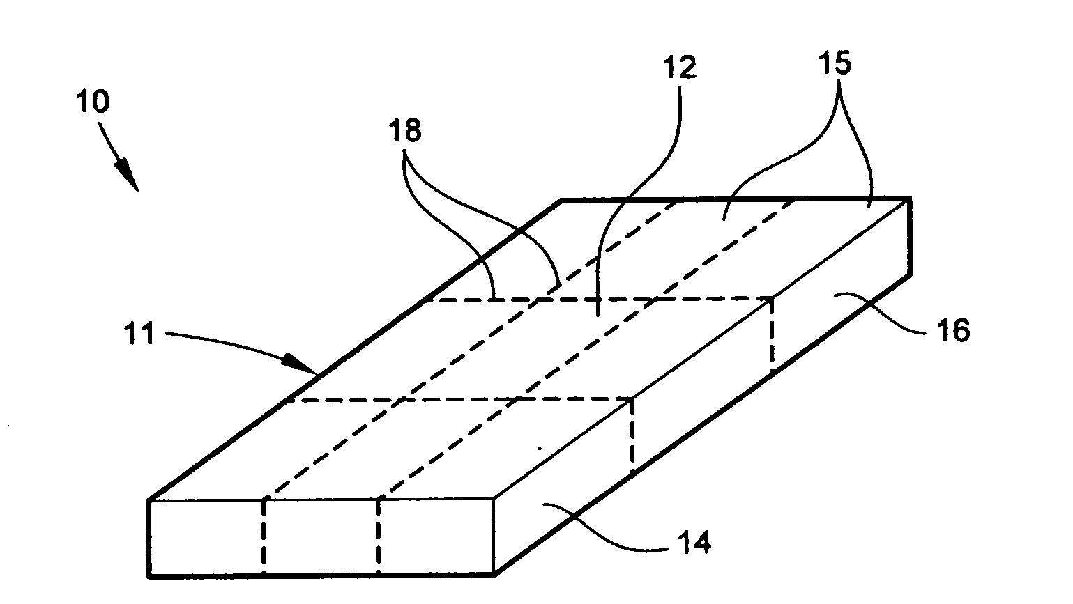
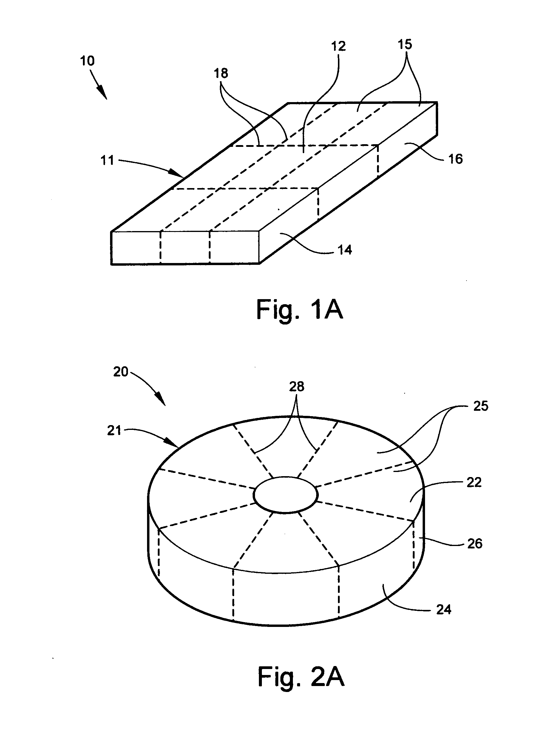
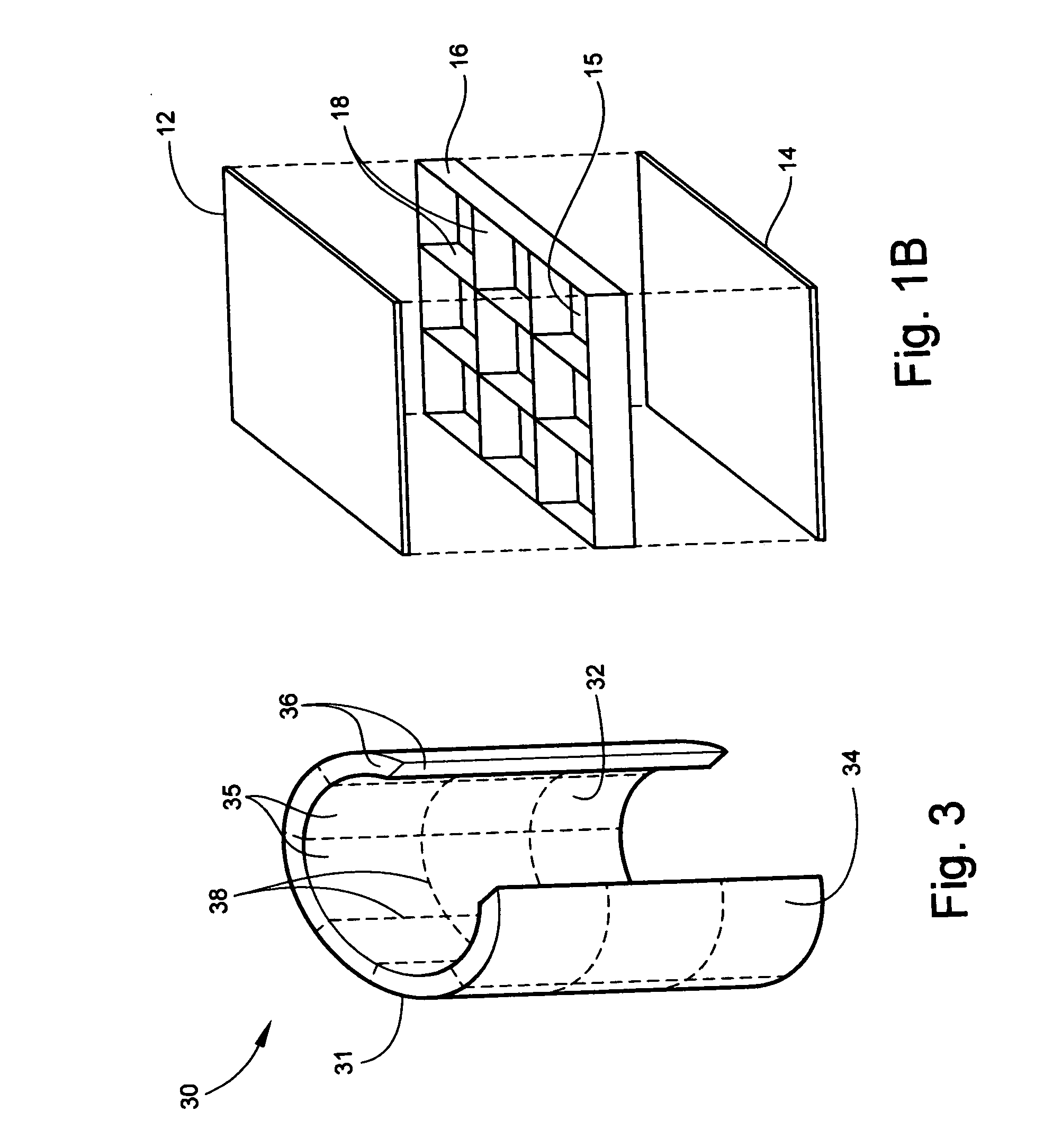
[0076]FIG. 1A through 3 depict the basic structure of the conformable battery architecture.

[0077]A thin walled, flat-plate, substantially rectangular battery 10 is depicted at FIGS. 1A and 1B. The battery 10 has an outer casing 11 consisting of a casing top 12, a casing bottom 14, and casing side walls 16.

[0078]A thin walled, flat-plate, circular battery 20 is depicted at FIGS. 2A and 2B. The battery 20, again, has an outer casing 21 consisting of a casing top 22, a casing bottom 24, and a casing circumferential wall 26.

[0079]A truncated, semi-cylindrical battery 30 is depicted at FIG. 3. The battery 30 has a casing 31 consisting of an inner casing wall 32, an outer casing wall 34, and casing side walls 36. The semi-cylindrical battery 30 of FIG. 3 is similar to the rectangular battery 10 of FIGS. 1A and 1B, with the plates curved to form the semi-cylindrical shape. (Hereinafter, with the exception of shape, the descriptions of the structure of the flat-plate battery 10 will apply e...


PUM

PropertyMeasurementUnit
shapeaaaaaaaaaa
structural stiffnessaaaaaaaaaa
internal pressureaaaaaaaaaa

Abstract

A conformable battery wherein the outer casing has an upper face plate, a lower face plate, and at least one perimetric wall, and an interior of the battery comprising a grid of walls extending from the upper face plate to the lower face plate and connecting to the at least one perimetric wall, thereby dividing the interior of the battery into at least two compartments and increasing the battery's structural stiffness and ability to sustain increased internal pressure. Each compartment contains an electrochemically active plate stack, and a network of electrical conductors provides electrical connection between the plate stacks in each of the compartment. The battery may further comprise a reservoir containing an acid additive which, when released into each of the compartments, shifts the battery from a low power mode into a high power mode.

Description

[0001]This application is related to U.S. patent application Ser. No. 10 / 456,625, filed on Jun. 9, 2003, which claims priority of U.S. Provisional Application No. 60 / 386,167, filed on Jun. 7, 2002. Elements of the Conformable Battery concept incorporate activation means described in the Bimodal Battery of U.S. Pat. No. 6,187,471, issued to the current inventor on Feb. 13, 2001, and are included herein by reference.BACKGROUND OF THE INVENTION[0002]1. Field of the Invention[0003]The present invention relates to batteries. More particularly, the invention comprises a battery which can be manufactured in a variety of shapes and geometries that can better utilize available space in specific applications.[0004]2. Description of the Prior Art[0005]Most high power, high energy density batteries used in the aerospace, defense, electric vehicle and other industries today consist of cylindrical or rectilinear, prismatic-shaped cells used singly, or connected in parallel or series into battery ...

Claims


Application Information

Patent Timeline
Patent Type & Authority Applications(United States)
IPC IPC(8): H01M8/00
CPCH01M2/1077H01M2/40H01M6/5077H01M6/5022H01M6/5038H01M6/32H01M50/77
Inventor MCDERMOTT, PATRICK P.
Owner MCDERMOTT PATRICK P
Learn More