Braided Peelable Sheath

a peelable, catheter technology, applied in the direction of lamination, chemistry apparatus and processes, catheters, etc., can solve the problems of increasing the difficulty and time requirement of medical procedures, and the wall structure of such catheters or sheaths is not readily splitable, so as to facilitate the splitting of the tubular body

Active Publication Date: 2009-02-12
ST JUDE MEDICAL ATRIAL FIBRILLATION DIV
View PDF7 Cites 22 Cited by
  • Summary
  • Abstract
  • Description
  • Claims
  • Application Information

AI Technical Summary

Benefits of technology

[0020]In one embodiment, the method includes placing a first polymer material in the first and second gaps that is at least somewhat different in composition from the a second polymer material used to form the inner and outer tubes. In one embodiment, the heat source creates a bond interface between the first and second materials, which creates a stress concentration that facilitates the splitting of the tubular body. In one embodiment, the first polymer material is more radiopaque than the second polymer material. In one embodiment, the first polymer material is a polymer loaded with biocompatible radiopaque filler of pure metal or metallic compound with at least one atomic number of from about 22 to about 83. In one embodiment, the first polymer material is a polymer loaded with tungsten.

Problems solved by technology

While a catheter or sheath with a reinforced wall structure offers superior ability to withstand the compression, tension and torque forces exerted on a catheter or sheath during a medical procedure, the wall structures of such catheters or sheaths are not readily splitable.
This increases the difficulty and time requirement for a medical procedure.

Method used


Image

  • Braided Peelable Sheath
  • Braided Peelable Sheath
  • Braided Peelable Sheath

Examples


first embodiment

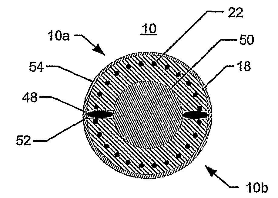
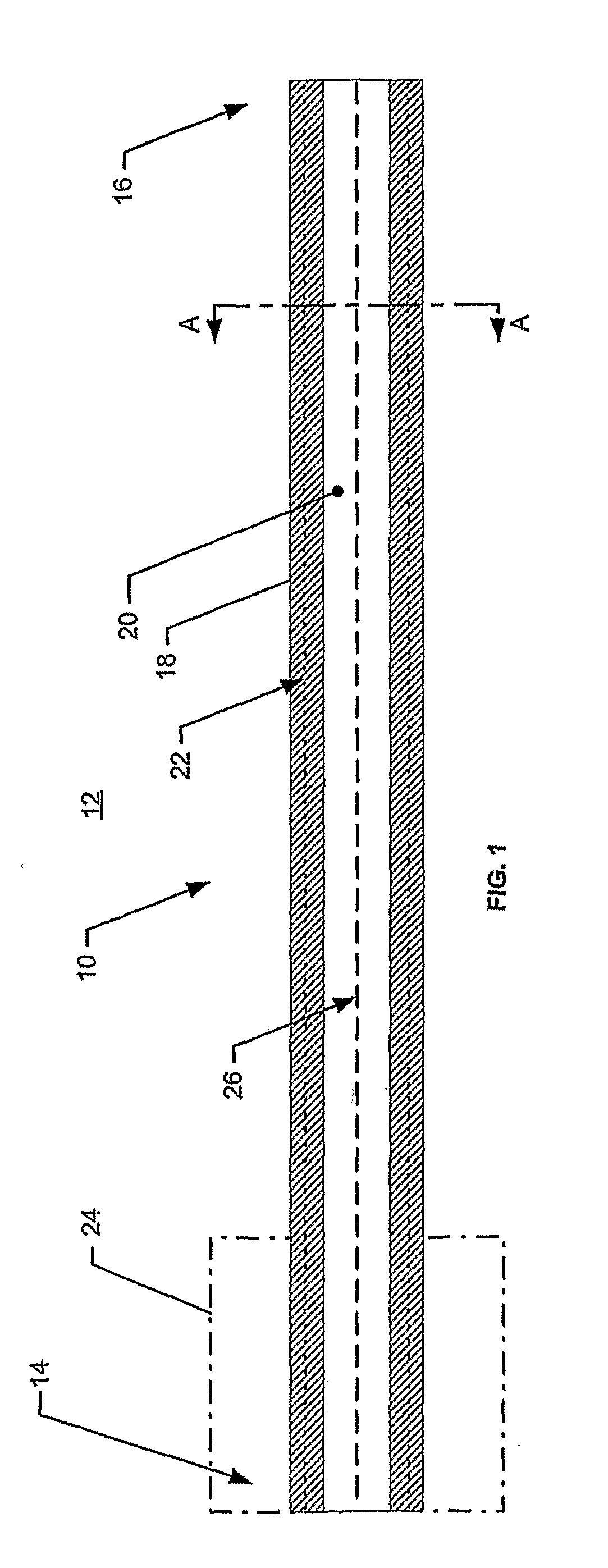
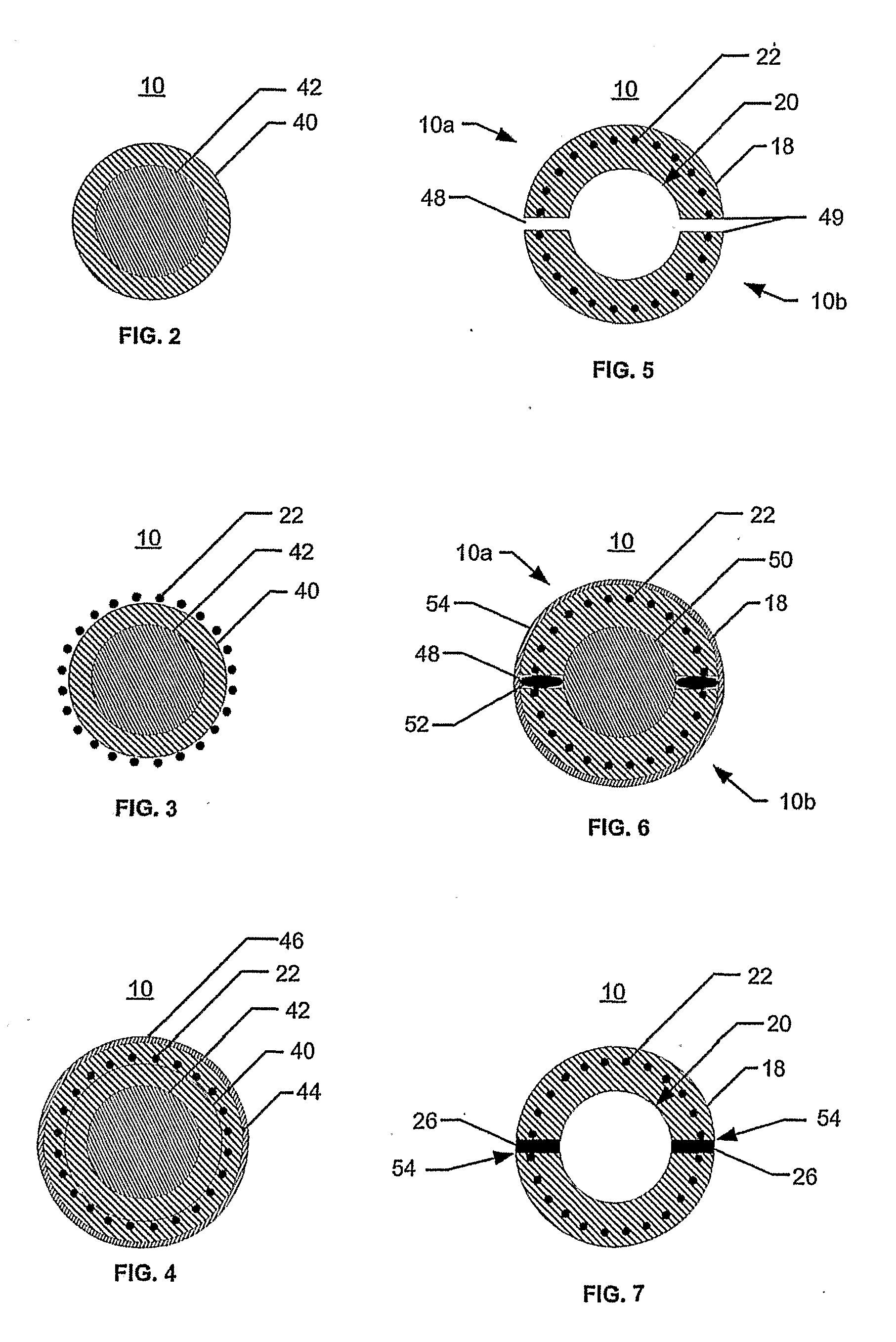
[0059]For a discussion of a method of manufacturing the tubular body 10, reference is now made to FIGS. 2-7 and 14. FIGS. 2-7 are latitudinal cross-sectional elevations of the tubular body 10 at various stages of the manufacturing process as if taken along section line AA in FIG. 1. FIG. 14 is a block diagram outlining the method pertaining to FIGS. 2-7.

[0060]As indicated in FIG. 2, an inner tube 40 with a wall thickness of approximately 0.0015-0.003 inches is slid over a mandrel 42 [block 200]. In one embodiment, the inner tube 40 is pre-extruded from a thermoplastic polymer (e.g., polytetrafluoroethylene “PTFE”, polyvinylidene fluoride “PVDF”, polyetheretherketone “PEEK”, etc.).

[0061]As illustrated in FIG. 3, a reinforcement layer 22 is slid over or wound / wrapped about the outer circumferential surface of the inner tube 40 [block 202]. In one embodiment, the reinforcement layer 22 is a braided or mesh layer made of stainless steel wire. The stainless steel wire may have a circular...

second embodiment

[0085]For a discussion of a method of manufacturing the tubular body 10, wherein the reinforcement layer 22 is not completely severed prior to final assembly, but is instead pre-stressed or pre-treated along the separation line or strip 26, reference is now made to FIGS. 16-21 and 28. FIGS. 16-21 are latitudinal cross-sectional elevations of the tubular body 10 at various stages of the manufacturing process as if taken along section line AA in FIG. 1. FIG. 28 is a block diagram outlining the method pertaining to FIGS. 16-21.

[0086]As shown in FIG. 16, an inner tube 40 of a flexible tubular body 10, which is similar in thickness and material to those previously described in this Detailed Description, is placed over a mandrel 42 [block 400]. In one embodiment, the inner tube 40 will have a single cut or gap 48a running the length of the tube 40. In another embodiment, the inner tube 40 will have two or more cuts or gaps 48a forming two or more inner tube sections 40a, 40b. For example,...


PUM

PropertyMeasurementUnit
atomic numberaaaaaaaaaa
flexibleaaaaaaaaaa
stress concentrationaaaaaaaaaa

Abstract

The present invention is a splitable/peelable reinforced flexible tubular body (10) for a catheter or sheath (12). The body (10) comprises a proximal end (14), a distal end (16), a wall structure (18), and a lumen (20) defined by the wall structure (18). The wall structure (18) extends between the ends and includes a reinforcement layer (22) within the wall structure (18) and a separation line (26) extending longitudinally along the wall structure (18). The separation line (26) is adapted to facilitate the splitting/peeling of the wall structure (18) to allow a medical device such as a pacemaker lead to be removed from within the tubular body (10).

Description

CROSS-REFERENCE TO RELATED APPLICATIONS[0001]The present application claims the benefit to U.S. Provisional Patent Application No. 60 / 690,270 (“the '270 application”), which was filed on 14 Jun. 2005. The '270 application is hereby incorporated by reference as though fully set forth herein.FIELD OF THE INVENTION[0002]The present invention relates to catheters and sheaths and methods of making and using catheters and sheaths. More particularly, the present invention relates to the flexible tubular bodies of steerable catheters or sheaths and methods of making and using such bodies.BACKGROUND OF THE INVENTION[0003]Catheters and sheaths having flexible tubular bodies with reinforced wall structures are utilized for introducing, positioning and implanting medical devices (e.g., pacemaker leads) within a patient. Once a medical device is implanted within a patient, the catheter or sheath must be withdrawn without causing displacement of the implanted medical device. Often, as in the case...

Claims


Application Information

Patent Timeline
Patent Type & Authority Applications(United States)
IPC IPC(8): A61M25/00B32B37/02
CPCA61M25/005A61M2025/0188A61M25/0668
Inventor STEHR, RICHARD E.GUO, XIAOPING
Owner ST JUDE MEDICAL ATRIAL FIBRILLATION DIV
Why Eureka
Try Eureka