Method of Arranging and Setting Spray Cooling Nozzles and Hot Steel Plate Cooling Apparatus

a technology of hot steel plate and cooling apparatus, which is applied in the direction of heat treatment apparatus, furnaces, manufacturing tools, etc., can solve the problems of unadjustable and achieve uniform distribution of cooling ability and cooling ability. uniform

Active Publication Date: 2009-02-19
NIPPON STEEL CORP
View PDF1 Cites 6 Cited by
  • Summary
  • Abstract
  • Description
  • Claims
  • Application Information

AI Technical Summary

Benefits of technology

[0007]Japanese Patent Publication (A) No. 6-238320 does not propose a method of making the cooling ability uniform for all spray cooling ranges provided in a plurality of lines in the processing direction and direction perpendicular to processing. Further, in Japanese Patent Publication (A) No. 8-238518, outside the nozzle spray interference regions, the cooling abilities become higher at the centers of the nozzle spray ranges, so even if using the cooling method of Japanese Patent Publication (A) No. 8-238518, a uniform distribution of cooling ability is not obtained. Further, in the method of Japanese Patent Publication (A) No. 2004-306064, when arranging spray nozzles, having distributions of cooling abilities in the coolant impact regions, in a line in the processing direction, despite the coolant spray impact regions being passed at least twice, a difference in cooling ability occurs between the centers of the impact regions and the ends of the impact regions and therefore a uniform distribution of cooling ability cannot be obtained.

Problems solved by technology

Further, in the method of Japanese Patent Publication (A) No. 2004-306064, when arranging spray nozzles, having distributions of cooling abilities in the coolant impact regions, in a line in the processing direction, despite the coolant spray impact regions being passed at least twice, a difference in cooling ability occurs between the centers of the impact regions and the ends of the impact regions and therefore a uniform distribution of cooling ability cannot be obtained.

Method used


Image

  • Method of Arranging and Setting Spray Cooling Nozzles and Hot Steel Plate Cooling Apparatus
  • Method of Arranging and Setting Spray Cooling Nozzles and Hot Steel Plate Cooling Apparatus
  • Method of Arranging and Setting Spray Cooling Nozzles and Hot Steel Plate Cooling Apparatus

Examples


examples

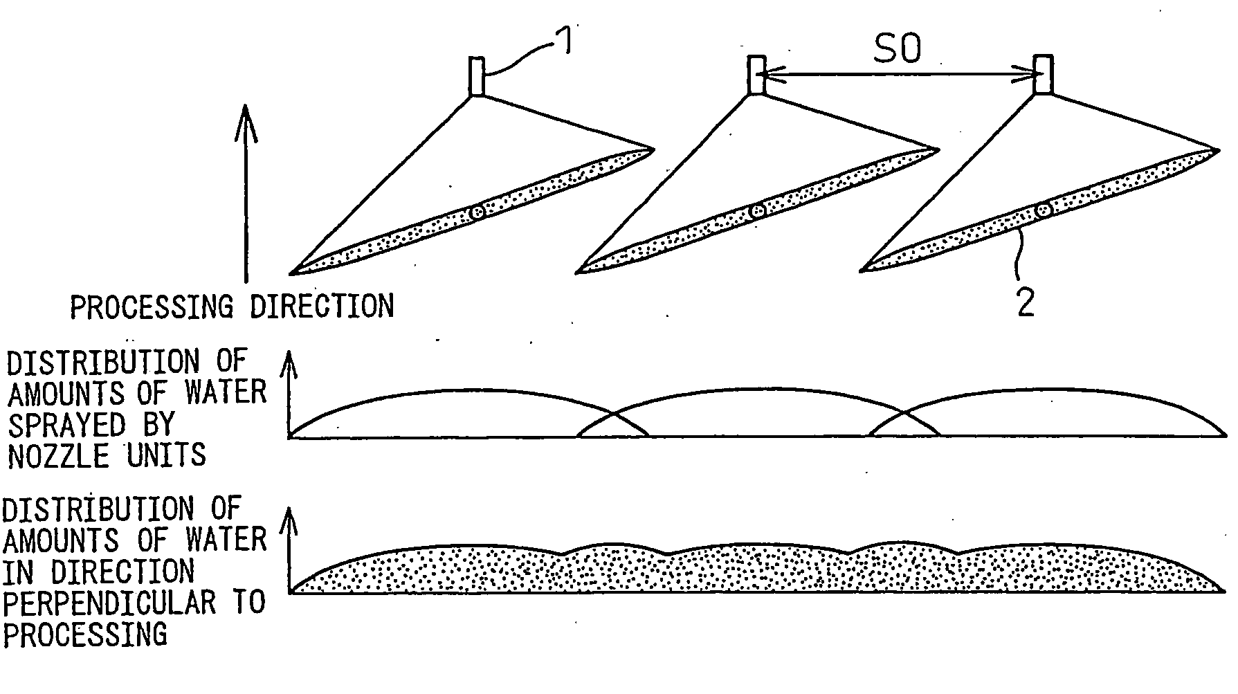
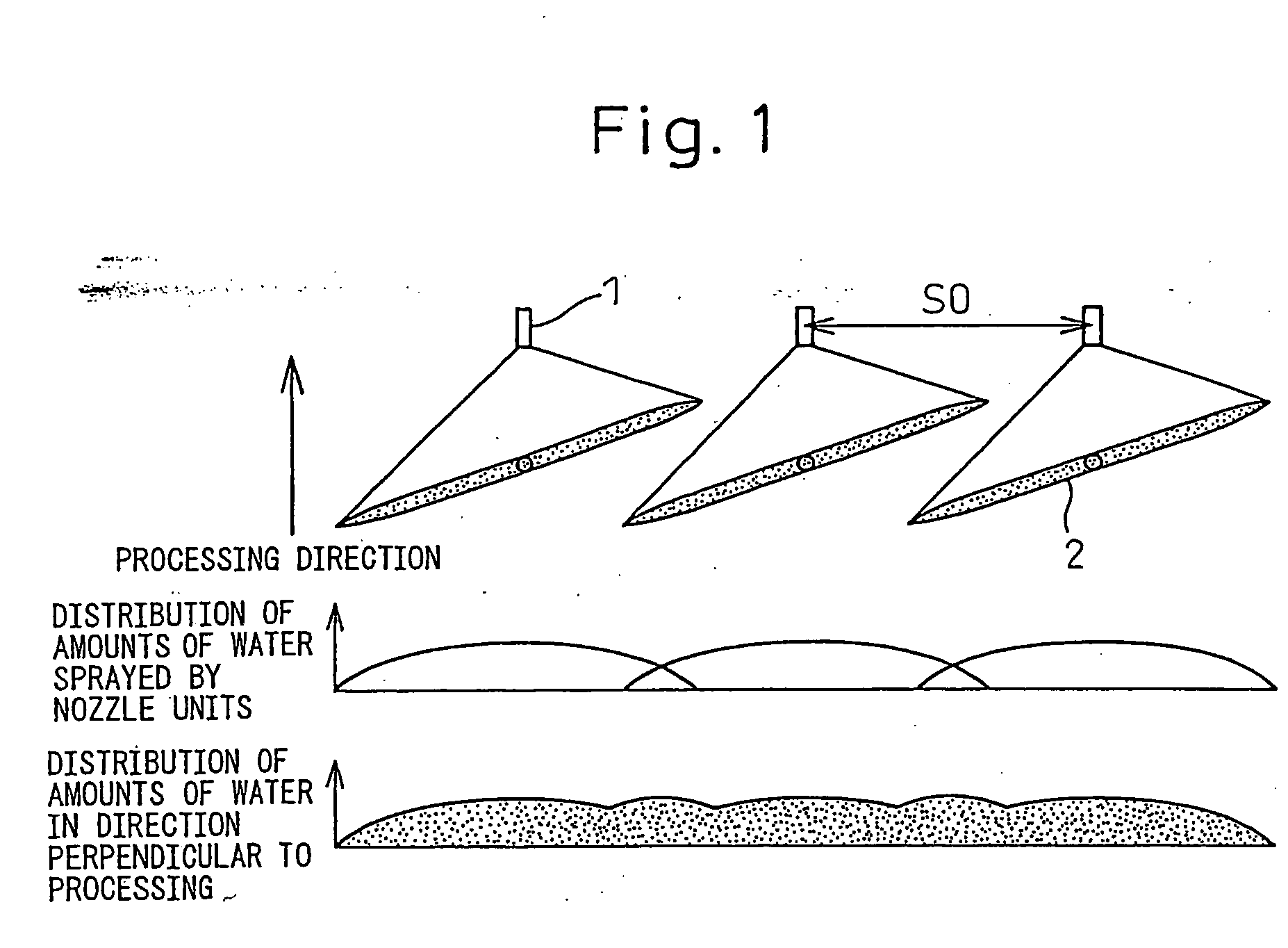
[0053]FIG. 10(a) and FIG. 10(b) show the arrangement of spray nozzles in a cooling test apparatus used for the study of the present invention. FIG. 10(a) shows a cooling apparatus arranging flat nozzles (spray nozzles 1) by the conventional method of arranging and setting spray nozzles so that the amounts of cooling water become the same in the direction perpendicular to processing, while FIG. 10(b) shows a cooling apparatus arranging oblong nozzles (spray nozzles 1) by the method of arranging and setting spray nozzles of the present invention so that the value of the n power of the impact pressures of the cooling water integrated in the processing direction becomes within −20% of the highest value in the direction perpendicular to processing. In this example, n=0.1. These cooling apparatuses were used for cooling tests and compared against each other. These used the same nozzle arrangements (S0=75 mm, L=150 mm) and amounts of water to cool rolled steel materials for general structu...


PUM

PropertyMeasurementUnit
pressureaaaaaaaaaa
flow rateaaaaaaaaaa
temperatureaaaaaaaaaa

Abstract

The present invention relates to an apparatus for cooling hot steel plate applied for controlled cooling of hot steel plate, obtained by hot rolling, while processing it constrained by constraining rolls and obtaining a steel material excellent and uniform in shape characteristics and provides a method of arranging and setting spray nozzles enabling uniform cooling in a direction perpendicular to processing and provides a method of arranging and setting spray nozzles of a spray cooling apparatus using two or more types of nozzles differing in amounts of water and spray regions to obtain a broad range of adjustment of amounts of water, wherein the spray nozzles are arranged so that a value of an n power of the impact pressures of the cooling water sprayed from the spray on the cooling surface integrated in the processing direction between pairs of constraining rolls becomes within −20% of the highest value in the direction perpendicular to processing,
    • where, 0.05≦n≦0.2

Description

TECHNICAL FIELD[0001]The present invention relates to a method of controlled cooling of hot steel plate, obtained by hot rolling, while processing it constrained by pairs of constraining rolls comprised of top and bottom constraining rolls, more particularly relates to an apparatus for cooling hot steel plate applied for obtaining a steel material excellent and uniform in shape characteristics.BACKGROUND ART[0002]To improve the mechanical properties, workability, and weldability of steel materials, the general practice has been for example to acceleratedly cool a high temperature state steel material right after being hot rolled while processing it on a rolling line and give the steel material a predetermined cooling history. However, the uneven cooling occurring when cooling a steel material becomes a cause of shape defects or work strain in the steel material. Fast improvement is desired to meet with the increasingly tougher demands for better quality of steel materials.[0003]To s...

Claims


Application Information

Patent Timeline
Patent Type & Authority Applications(United States)
IPC IPC(8): C21D8/04C21D1/62
CPCB21B45/0233B21B45/0218B21B45/02B21B45/08
Inventor YAMAMOTO, RYUJISERIZAWA, YOSHIHIROOGAWA, SHIGERUUENO, HIRONORIDOKI, MASAHIRONISHIYAMA, YASUHIRO
Owner NIPPON STEEL CORP
Why Eureka
Try Eureka