Synchronization of Spectrum Analyzer Frequency Sweep and External Switch

Inactive Publication Date: 2009-02-19
AGILENT TECH INC
View PDF0 Cites 10 Cited by
  • Summary
  • Abstract
  • Description
  • Claims
  • Application Information

AI Technical Summary

Problems solved by technology

However, more modern spectrum analyzers no longer use this RS232 bus receiver and therefore it would be desirable to find ano

Method used


Image

  • Synchronization of Spectrum Analyzer Frequency Sweep and External Switch
  • Synchronization of Spectrum Analyzer Frequency Sweep and External Switch
  • Synchronization of Spectrum Analyzer Frequency Sweep and External Switch

Examples


Embodiment Construction

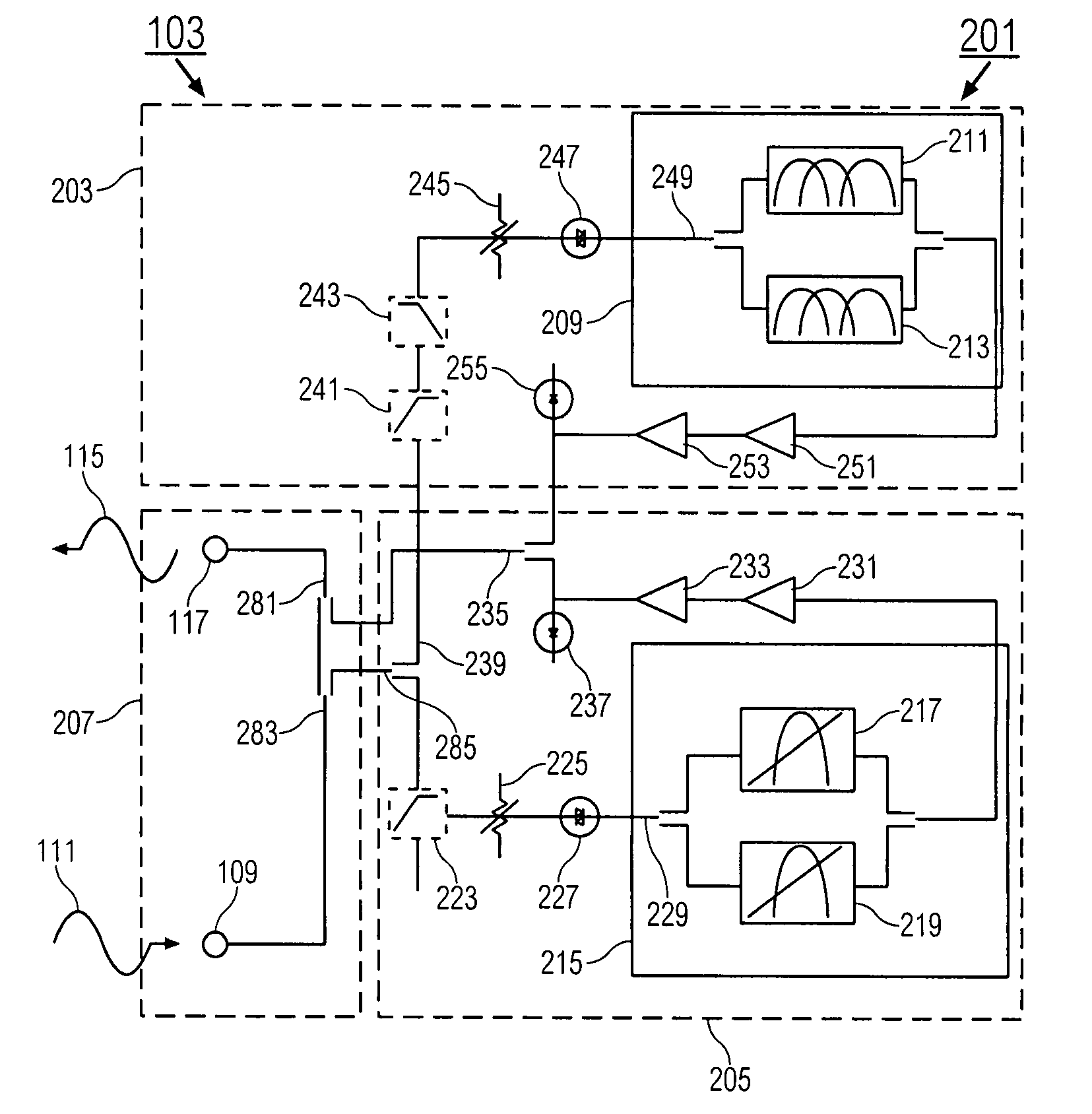
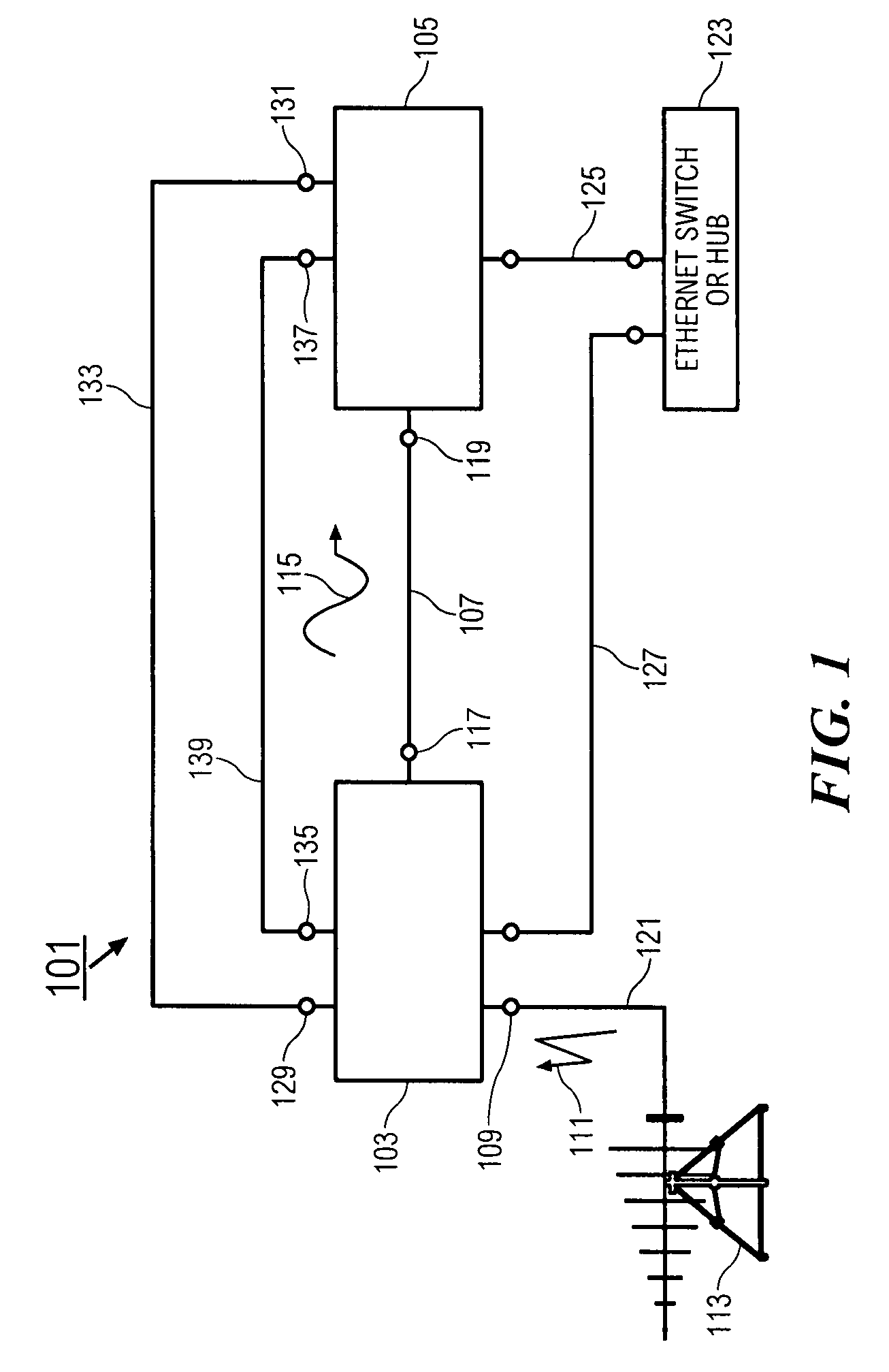
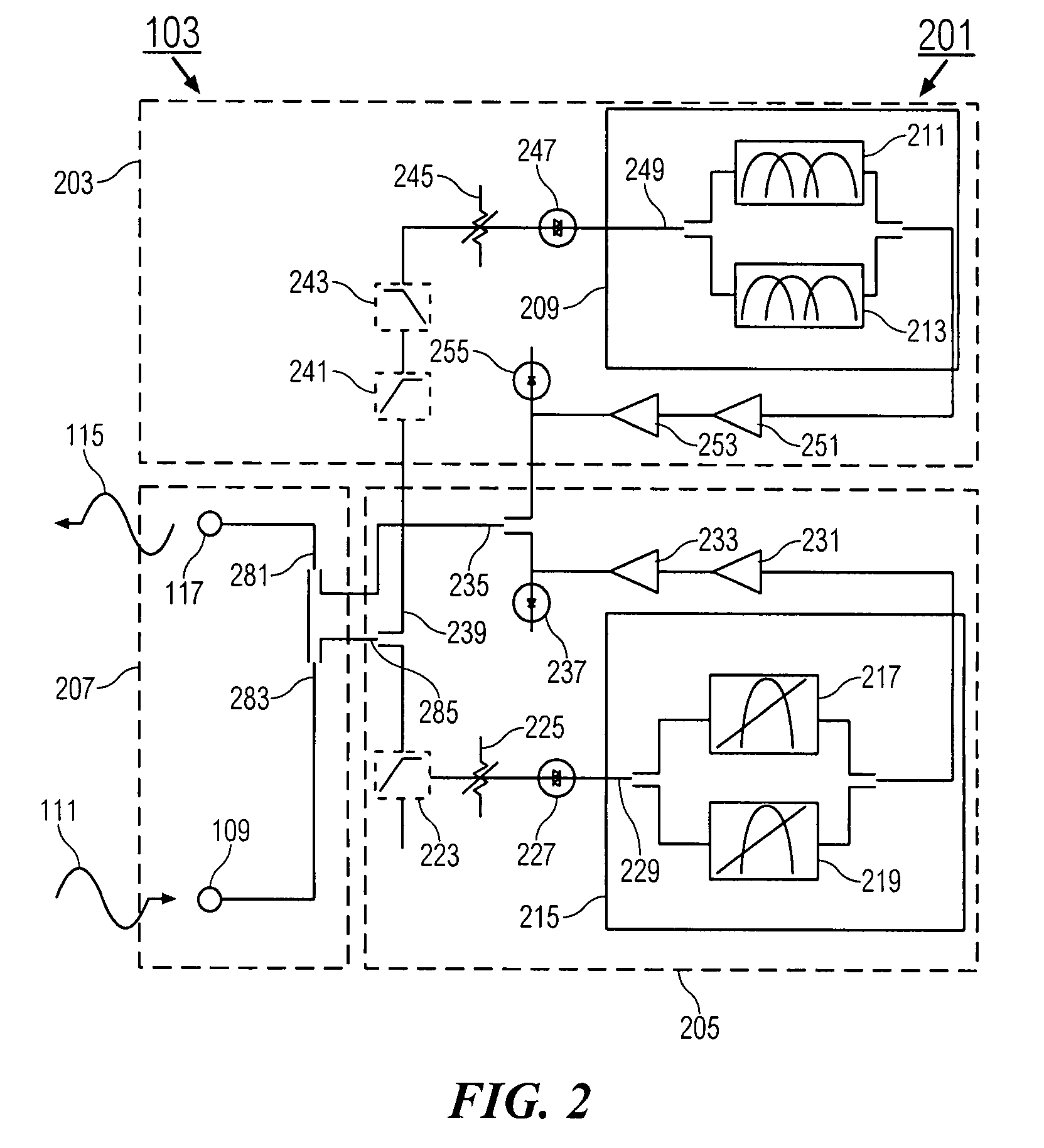
[0019]FIG. 1 is a schematic block diagram showing components making up a CISPR 16 compliant EMI receiver 101 of the present invention. The components include a preselector 103 and a spectrum analyzer 105. In general the spectrum analyzer 105 can be selected from different types of signal analyzers and the EMI receiver 101 can be selected from different types of measurement receivers.

[0020]The preselector 103 pre-filters broadband signals so that the combination of the preselector 103 and spectrum analyzer 105 becomes an EMI receiver 101 for measuring impulsive EMI signals with high dynamic range and accuracy, as specified by CISPR 16. In the operation of the EMI receiver 101, a radiated or conducted emissions signal 111 to be measured is transmitted from a source 113 through an RF cable 121 and to a preselector RF input port 109 of the preselector 103. The source 113 can be an antenna receiving radiated emission signals, for example, or can be a cable transmitting conducted emission...


PUM


Abstract

A measuring receiver comprises a spectrum analyzer having a local oscillator for sweeping the measurement frequency of the spectrum analyzer through multiple frequency bands. A preselector has multiple filter paths with frequency bands corresponding to frequency bands of the spectrum analyzer. The filter paths for passing signals through the preselector and outputting filtered signals to the spectrum analyzer. Switches of the preselector switch between filter paths to switch in a filter path having a frequency band corresponding to a frequency band being swept by the spectrum analyzer. A controller delays the sweeping of the measurement frequency during intervals when the switches are switching between filter paths.

Description

BACKGROUND OF THE INVENTION[0001]Any product that uses the public power grid or has electronic circuitry must pass EMC (electromagnetic compatibility) requirements. EMC is essentially the opposite of EMI (electromagnetic interference). EMC means that the device is compatible with (i.e., no interference caused by) its EM environment, and it does not emit levels of electromagnetic energy that cause EMI in other devices in the vicinity. Compliance with these emission requirements requires radiated emissions testing and conducted emissions testing. EMI receivers are used to measure the characteristics of these products to make sure that they meet the emissions requirements.[0002]Herein “measurement receiver” or “measuring receiver” is defined as a system used to examine the spectral composition of some electrical, acoustic, or optical waveform. EMI receivers are thus a subset of “measuring receivers”.[0003]Radiated emissions testing looks for signals being emitted from the equipment und...

Claims


Application Information

Patent Timeline
IPC IPC(8): G01R23/00
CPCG01R23/165
Inventor HEAH, KOOI SEOWLIM, WEI BEESIM, YEW TATT
Owner AGILENT TECH INC
Why Eureka
Try Eureka