Overcurrent limitation and output short-circuit protection circuit, voltage regulator using overcurrent limitation and output short-circuit protection circuit, and electronic equipment

a voltage regulator and protection circuit technology, applied in the direction of electric variable regulation, electrical equipment, instruments, etc., can solve the problems of large area of switching units disadvantageously becoming large, complicated circuit of conventional voltage regulators, and difficulty in considering phase compensation design consideration

Inactive Publication Date: 2009-02-19
RICOH KK
View PDF3 Cites 25 Cited by
  • Summary
  • Abstract
  • Description
  • Claims
  • Application Information

AI Technical Summary

Benefits of technology

[0015]In view of the above circumstances, the present invention may realize output short-circuit protection without using a fold-back mode so as to provide an overcurrent protection and output short-circuit protection circuit that is easily designed and capable of being realized by a small circuit with low power consumption, a voltage regulator using the overcurrent protection and output short-circuit protection circuit, and various electronic equipment items such as mobile electronic devices including mobile phones, in-vehicle electric components, and home electric appliances.

Problems solved by technology

However, it is difficult to design the phase compensation in consideration of variations in manufacturing.
However, in the case of an IC having an output current of 1 A or larger, the area of the switching unit disadvantageously becomes large so as to make the resistance value of the switching unit much smaller than the resistance value of the current voltage conversion unit.
The circuit of a conventional voltage regulator is complicated because it requires the overcurrent protection circuit and the output short-circuit protection circuit.
In addition, it is difficult to design the voltage regulator because the fold-back mode of the output short-circuit protection circuit requires the phase compensation.
Therefore, as the output current of the output transistor M1 increases, the power consumption of the IC increases proportionately.

Method used


Image

  • Overcurrent limitation and output short-circuit protection circuit, voltage regulator using overcurrent limitation and output short-circuit protection circuit, and electronic equipment
  • Overcurrent limitation and output short-circuit protection circuit, voltage regulator using overcurrent limitation and output short-circuit protection circuit, and electronic equipment
  • Overcurrent limitation and output short-circuit protection circuit, voltage regulator using overcurrent limitation and output short-circuit protection circuit, and electronic equipment

Examples


Embodiment Construction

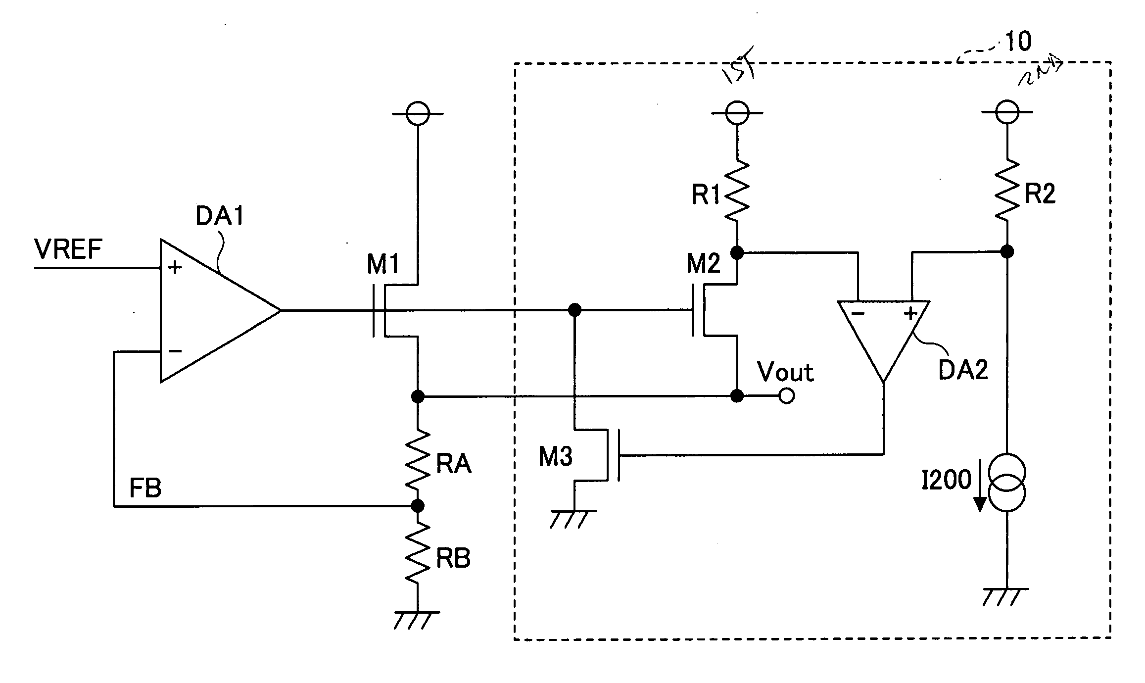
[0041]FIG. 3 is a diagram showing the embodiment of a first basic circuit of the present invention.

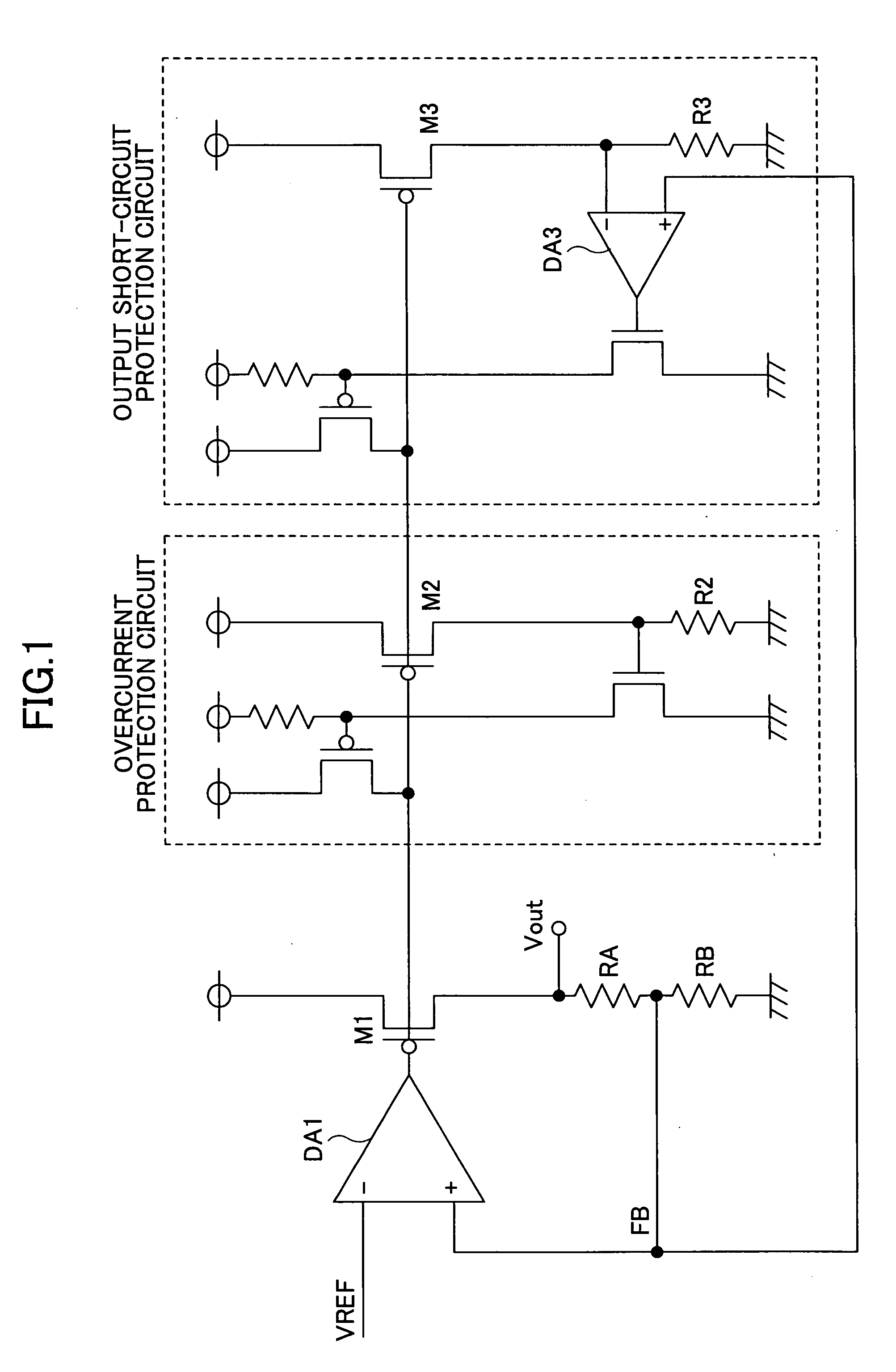
[0042]As shown in FIG. 3, the overcurrent protection (hereinafter referred also to as over current limitation) circuit of a DC stabilized power supply circuit according to this embodiment drives an output transistor M1 so as to make an output voltage constant based on the output of a differential amplifier DA1 that amplifies a difference between a reference voltage VREF and a voltage FB proportional to the output voltage.

[0043]Furthermore, the overcurrent protection circuit has a proportional output current generation unit (transistor) M2 that generates a current proportional to a current flowing to the output transistor M1 and a current voltage conversion unit (resistor) R1 that converts the output current of the proportional output current generation unit M2 into a voltage, which are connected in series between a first power supply terminal and an output terminal Vout.

[0044]Furthermo...


PUM


Abstract

A disclosed overcurrent protection and output short-circuit protection circuit has a proportional output current generation unit and a first current voltage conversion unit provided in series between a first power supply terminal and an output terminal. Furthermore, the overcurrent protection and output short-circuit protection circuit has a control unit that operates based on a difference between a voltage generated at the first current voltage conversion unit and that generated at a second current voltage conversion unit provided between the first power supply terminal and a second power supply terminal. A current flowing to the second current voltage conversion unit is changed by one or more switching elements in a stepwise manner based on the output voltages of the output transistor when supplying the current, thereby changing the voltages generated at both ends of the second current voltage conversion unit.

Description

BACKGROUND OF THE INVENTION[0001]1. Field of the Invention[0002]The present invention relates to a technique for an overcurrent limitation and output short-circuit protection circuit of a voltage regulator and, in particular, to an overcurrent protection and output short-circuit protection circuit that is easily designed and capable of being realized by a small circuit with low power consumption, a voltage regulator using the overcurent limitation and output short-circuit protection circuit, and various electronic equipment items such as mobile electronic devices including mobile phones, in-vehicle electric components, and home electric appliances.[0003]2. Description of the Related Art[0004]As overcurrent protection circuits of a power supply circuit, for example, disclosures in JP-A-2006-178539 (Patent Document 1) and JP-B2-3782726 (Patent Document 2) have been proposed.[0005]JP-A-2006-178539 (Patent Document 1) discloses a technique for protecting an IC (Integrated Circuit) with ...

Claims


Application Information

Patent Timeline
Patent Type & Authority Applications(United States)
IPC IPC(8): H02H9/02G05F1/569
CPCG05F1/573
Inventor MORINO, KOICHI
Owner RICOH KK
Why Eureka
Try Eureka