Method and Apparatus for Optimization of Distributed Generation

a distributed generation and optimization technology, applied in the direction of wind energy generation, process and machine control, emergency supply, etc., can solve the problems of wild spikes in prices and inefficient energy consumption, and achieve the effect of minimizing the total cost of electricity

Active Publication Date: 2009-02-19
INTELLIGENT GENERATION
View PDF4 Cites 149 Cited by
  • Summary
  • Abstract
  • Description
  • Claims
  • Application Information

AI Technical Summary

Benefits of technology

[0023]Z may then represent the goal of minimizing the total cost of electricity to a building within the context of producing and maintaining a user-selected supply of electricity that does or does not take into account transportation fuel needs. Y2 may represent the available supply of electricity from renewable sources. Y3 may represent the requirement of electricity from the grid. The constants b1 and b2 are the per unit costs of obtaining electricity from renewable sources and electricity from the grid, respectively. This less robust example embodiment is consistent with the first example embodiment except that the X1 and Y1 factors for natural gas are not considered.

Problems solved by technology

In the traditional arrangement, the independence of electricity, natural gas and gasoline combined with the daily and seasonal variations in peak supply and demand make energy consumption inefficient.
The variability of many factors related to supply of, demand for and price of the energy sources can often result (as we experience routinely) in wild spikes in price.

Method used


Image

  • Method and Apparatus for Optimization of Distributed Generation
  • Method and Apparatus for Optimization of Distributed Generation
  • Method and Apparatus for Optimization of Distributed Generation

Examples


Embodiment Construction

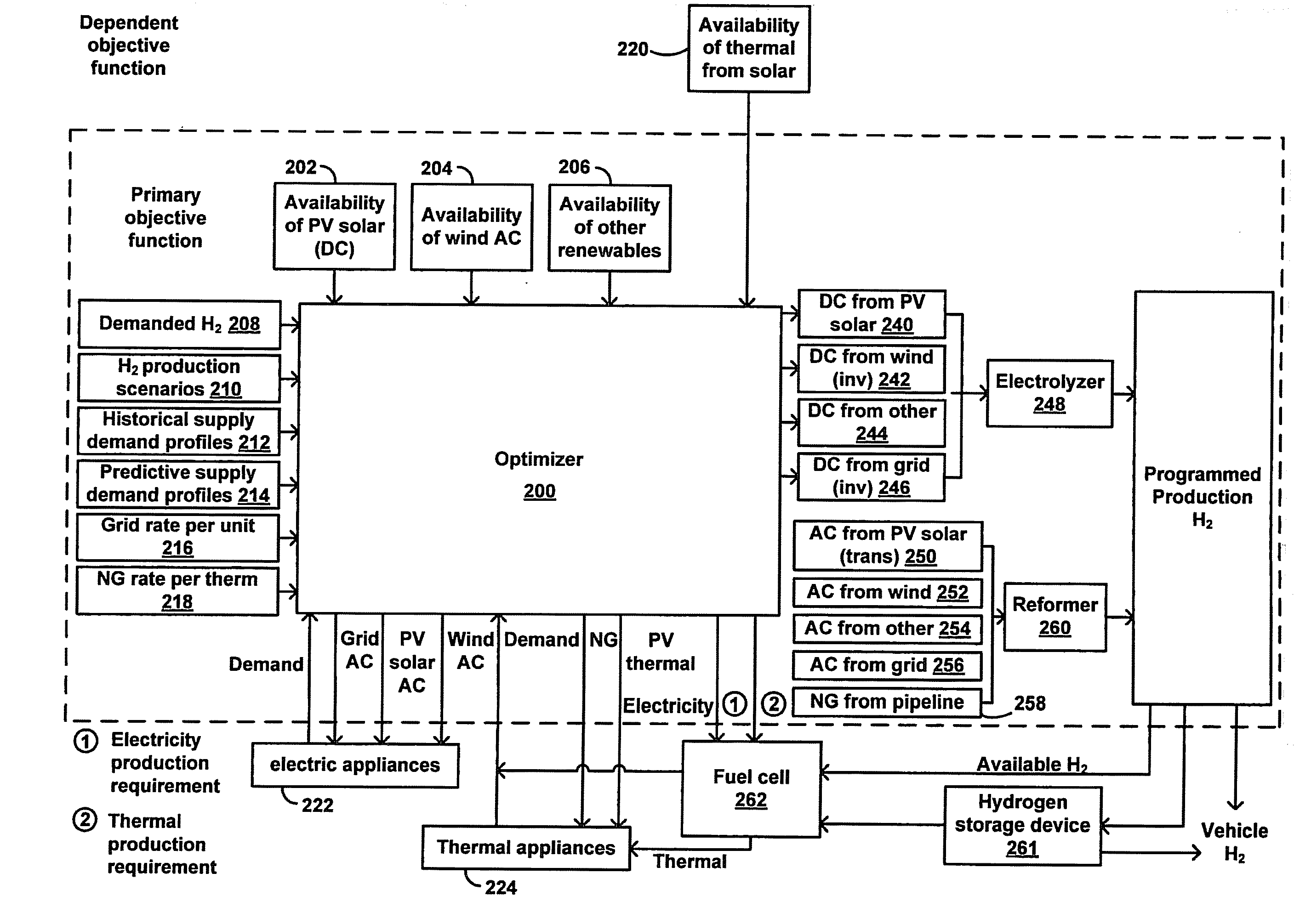
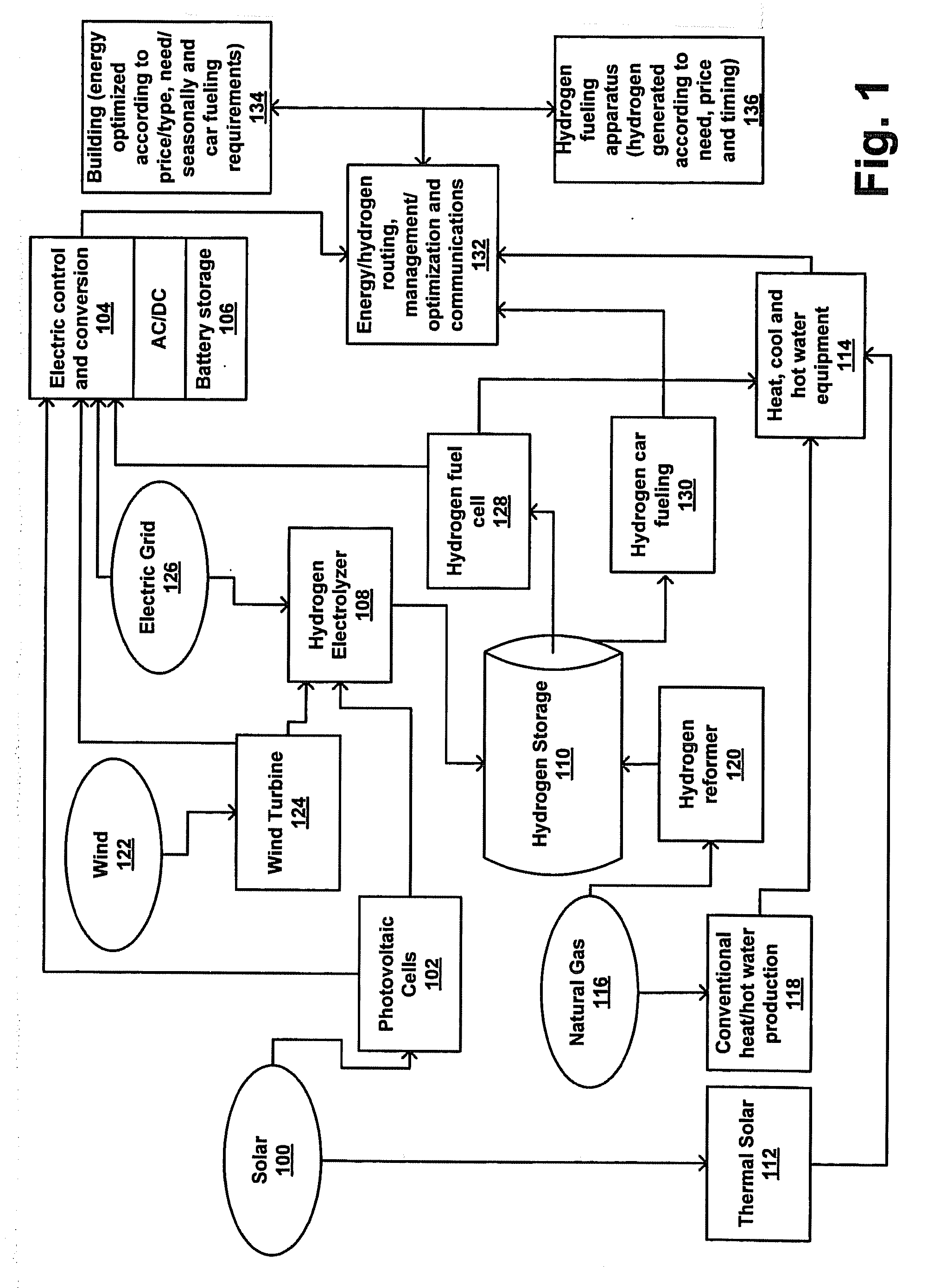
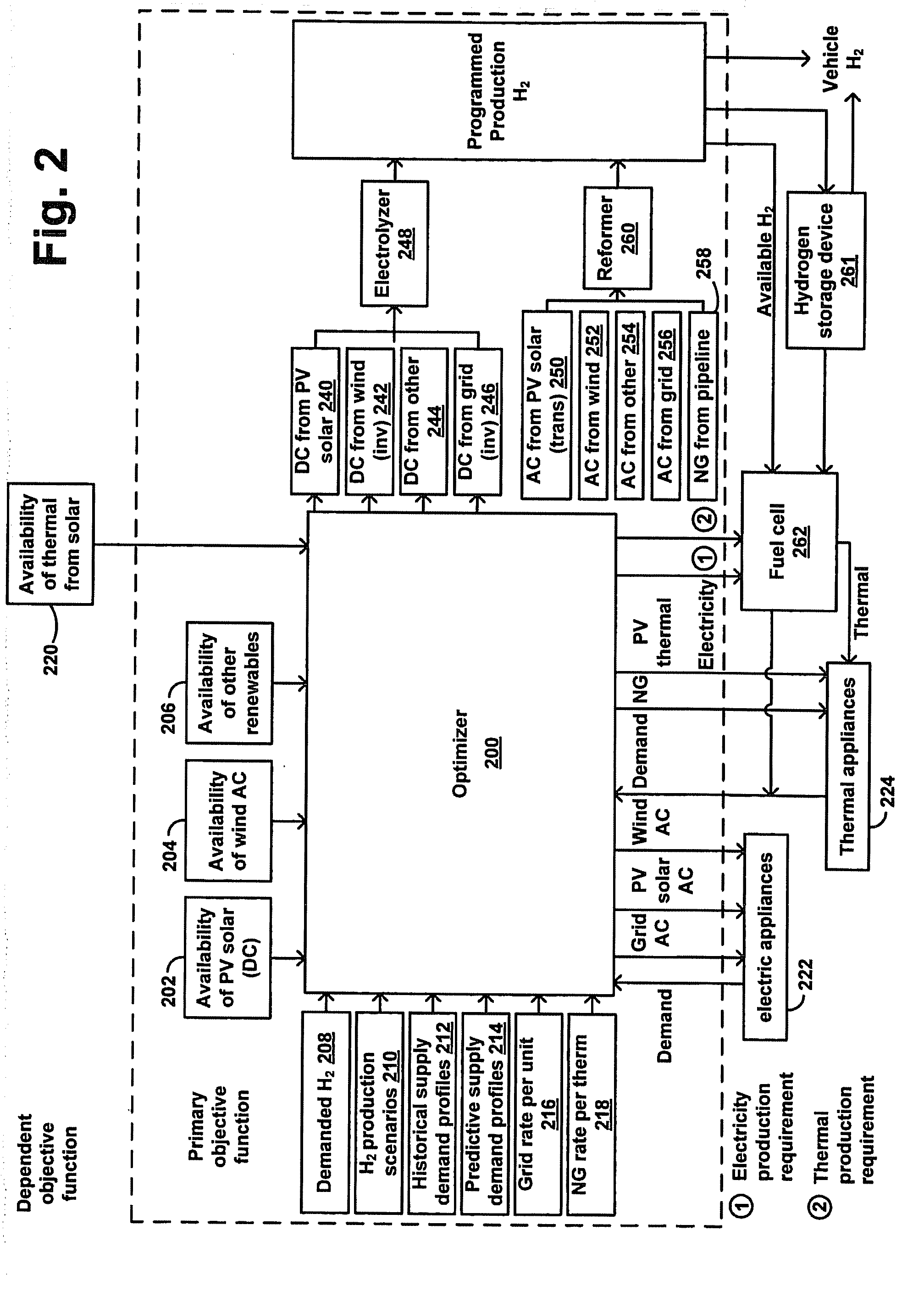
[0033]An energy optimization system may be used in a building or a group of buildings to minimize total energy costs by optimizing the use of utility-supplied energy and alternative source energy. At the same time, the system may produce and store energy that can be used to fuel vehicles, to independently produce electricity and / or thermal energy, or both.

[0034]In a robust embodiment, the system might be implemented in a programmable, microprocessor-based unit that monitors the production of hydrogen, thermal energy and electricity from renewable sources, current stores of hydrogen, current and expected thermal and electricity requirements of a building, current and expected electricity load of the equipment used to process hydrogen, expected thermal and electricity generating capacity of the renewable sources, per unit costs (both seasonal and time of day) of conventional (e.g., utility-based) energy sources, and hydrogen requirements for refueling to assess an optimal mix of renew...


PUM


Abstract

An energy optimization method and control apparatus may be used in a single building or a group of buildings to optimize utility-supplied and renewable sources in order to minimize the total energy cost. Simultaneously, it may also produce and store energy, such as electricity or hydrogen, that can be used to fuel vehicles, provide a means for independent production of household energy needs, or both. Various factors, such as the production of thermal energy and electricity from the renewable sources, the current store of stored energy, the current and expected thermal and electricity requirements of the building (based on a profile), the current and expected electricity loads of the equipment used to process stored energy, the expected thermal and electricity generating capacity of the renewable sources and other factors can be used to determine the mix of renewable-based and utility-based energy that minimizes the total energy cost.

Description

CROSS-REFERENCE TO RELATED APPLICATION[0001]This application is a continuation-in-part of application Ser. No. 10 / 867,969 filed on Jun. 15, 2004, the content of which is fully incorporated herein by reference.FIELD OF THE INVENTION[0002]The invention relates to energy generation and storage systems. More specifically, it relates to an intelligent distributed generation system for optimizing utility-supplied electricity, natural gas, and production and storage of energy for later use to minimize a total energy cost.BACKGROUND OF THE INVENTION[0003]Most residences and small commercial establishments, inclusive of single-family homes, multi-family dwellings, and residential communities, require electricity and natural gas that is provided by connections to local utilities. Electricity is typically provided from a utility grid, and it can be used to power electric appliances. Natural gas is typically provided from a natural gas utility, and it can provide thermal heat for appliances, cl...

Claims


Application Information

Patent Timeline
Patent Type & Authority Applications(United States)
IPC IPC(8): G06F17/00
CPCH01M8/0612Y02B10/14H01M8/0656H01M2250/10H01M2250/402H01M2250/405H02J15/00Y02B90/12Y02B90/14Y02E70/10Y02E70/30Y02E60/50Y02B90/16H02J7/34H02J2001/004H02J3/383H02J3/386H02J3/382Y02E10/563Y02E10/763H01M8/065H02J2300/30H02J2300/40H02J2300/28H02J2300/20H02J2300/24H02J3/381Y02B10/10Y02B90/10Y02E10/56Y02E10/76Y02E60/36H02J15/008
Inventor MARHOEFER, JOHN JOSEPH
Owner INTELLIGENT GENERATION
Why Eureka
Try Eureka