
Tool and method for pulling and cutting a Z-axis electrical interconnector

a technology of z-axis and electrical interconnection, which is applied in the direction of manufacturing tools, metal working apparatus, printed circuit aspects, etc., can solve the problems of difficult coordination of the functionality of two independently operating machines, difficult handling of twist pins, and complex electronic sensors and controllers, and achieve the effect of convenient execution

Inactive Publication Date: 2009-02-26
MEDALLION TECH
View PDF13 Cites 8 Cited by
  • Summary
  • Abstract
  • Description
  • Claims
  • Application Information

AI Technical Summary

Benefits of technology

[0014]The present invention combines the pulling and cutting functions necessary to assemble a z-axis interconnector into vias of a plurality of stacked printed circuit boards in a series of sequentially-executed operations. The operations involved in pulling and cutting the z-axis interconnector are conveniently executed by a single, relatively small and hand-manipulated mobile machine. The pulling and cutting operations are interrelated so that each z-axis interconnector is assembled in a reliable, consistent and efficient manner. The relatively small size of the pulling and cutting tool allows it to be manipulated by hand, so that an individual can create three-dimensional circuit modules without using large, immobile, expensive and separate assembly-line machines which must be coordinated in functionality with a complex control system. Instead, the present invention is capable of implementation as a hand tool, while still obtaining all the precision and functionality necessary to assemble z-axis interconnectors into a three-dimensional electronic module. The invention can also be implemented as a stationary tool for use in an assembly line if desired, for example.

Problems solved by technology

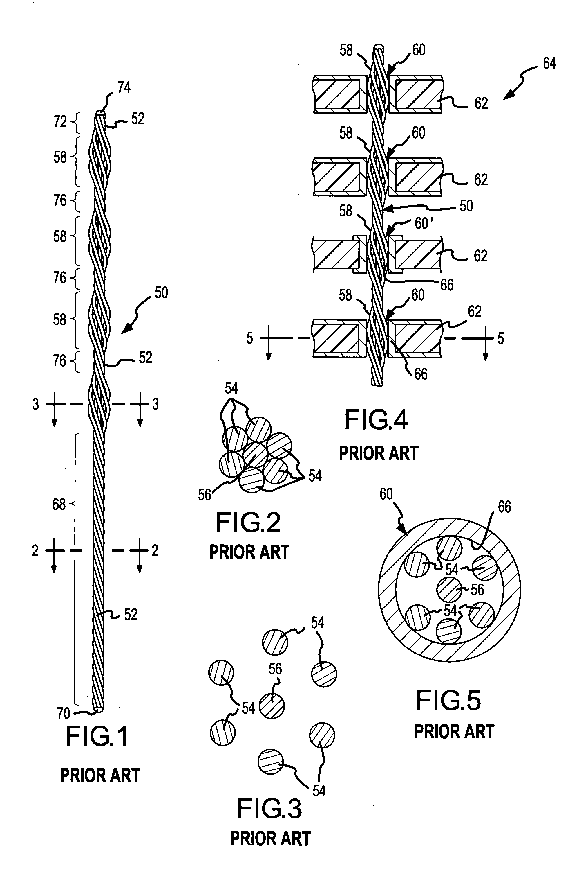
The weight of a typical four-bulge twist pin is about 0.0077 grams, making it so light that handling the twist pin is very difficult.
Coordinating the functionality of two independently operating machines is difficult, and generally requires very complex electronic sensors and controllers.
Furthermore, because the operation of the pulling and cutting machines are independent of one another, the functionality of one machine may adversely influence the proper functionality of the other machine.
Consequently, it is impossible, expensive or extremely inconvenient to assemble three-dimensional circuit modules other than by use of this type of assembly-line equipment.
The expense of programming the separate stationary machines is not conducive to the use of the z-axis interconnectors to assemble relatively smaller numbers of modules.

Method used


Image

  • Tool and method for pulling and cutting a Z-axis electrical interconnector
  • Tool and method for pulling and cutting a Z-axis electrical interconnector
  • Tool and method for pulling and cutting a Z-axis electrical interconnector

Examples


Embodiment Construction

In General

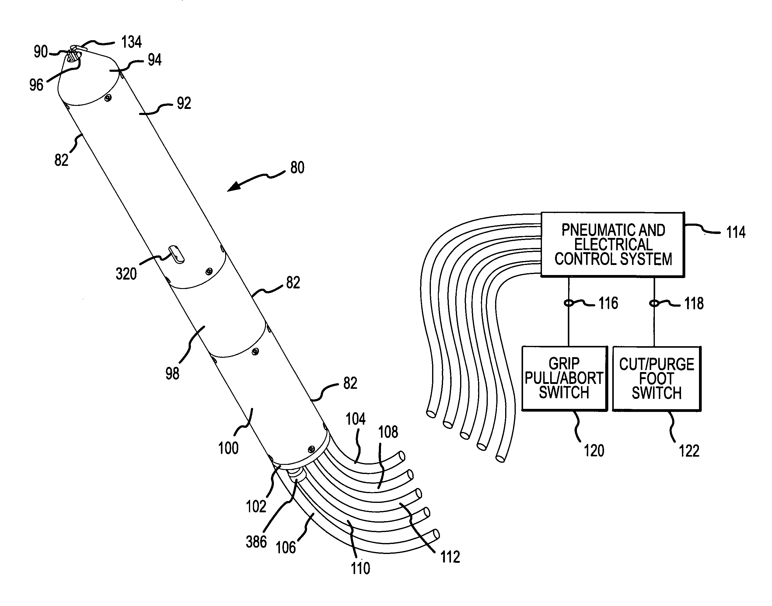
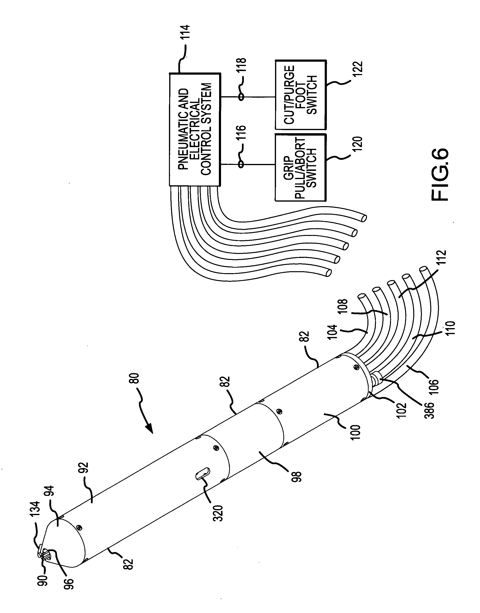
[0046]A twist pin pulling and cutting tool 80 incorporating the present invention is shown in FIGS. 6 and 7. The tool includes a housing 82, within which a gripping and cutting subassembly 84, a longitudinal movement subassembly 86 and a pneumatic interface and leader collection subassembly 88 are located. The gripping and cutting subassembly 84 includes a pinch and cut blade 90 located at a forward end thereof. A front shell 92 of the housing 82 generally covers the gripping and cutting subassembly 84, as shown in FIG. 7. A conically shaped front end cap 94 attaches to the front shell 92, and an opening 96 is formed in the front end cap 94 to permit the pinch and cut blade 90 to extend from the housing 82 and interact with the leader 68 of the twist pin 50 (FIGS. 1 and 9A-9F) during assembly of the twist pin 50 into its final position within the module 64 (FIGS. 4 and 9F).

[0047]The longitudinal movement subassembly 86 connects to the gripping and cutting subassembly 84 wi...


PUM

PropertyMeasurementUnit
lengthaaaaaaaaaa
lengthaaaaaaaaaa
weightaaaaaaaaaa

Abstract

A connection portion of a z-axis interconnector is assembled into contact with a plurality of aligned vias in a corresponding plurality of stacked printed circuit boards by gripping and pulling a leader portion of the interconnector connected to the connection portion, to move the interconnector into the final position with the connection portion contacting the aligned vias. The leader portion is severed from the connection portion after the interconnector is moved into the final position. A single pulling and cutting tool which accomplishes these functions preferably does so by a single pinch and cut device having opposing blades which partially penetrate into the leader portion to grip the leader portion, which fully penetrated through the leader portion to sever the leader portion, and which are moved toward and away from the plurality of stacked printed circuit boards to pull the interconnector and to reposition for severing the leader portion.

Description

[0001]This invention relates to assembling three-dimensional electronic modules, and more particularly to a new and improved tool and method for pulling z-axis interconnectors into predetermined positions between circuit boards of the module and thereafter cutting off an excess portion of each the z-axis interconnector in a single sequence of operations executed rapidly and efficiently to mechanically and electrically connect the circuit boards and assemble the module. The z-axis interconnectors are preferably twist pins, which are of the type, and are used in the manner, described in U.S. Pat. Nos. 4,955,523, 5,014,419, 5,054,192, 5,045,975, 5,112,232, 5,184,400, 5,189,507, 5,195,237, 6,528,759, 6,530,511, 6,584,677, 6,716,038, 6,729,026 and 6,971,415, all of which are owned by the assignee of the present invention. The subject matter of these prior patents is incorporated herein by this reference.BACKGROUND OF THE INVENTION[0002]The evolution of computer and electronic systems has...

Claims


Application Information

Patent Timeline
Patent Type & Authority Applications(United States)
IPC IPC(8): H01R43/00H05K3/36H01R43/20
CPCH01R43/205Y10T29/49126H05K3/368H05K2201/096H05K2201/10287H05K2203/0195H01R12/523Y10T29/53217Y10T29/49153Y10T29/53209Y10T29/53213Y10T29/5193Y10T29/49194Y10T29/49117H05K3/308H01R43/20
Inventor GARCIA, STEVEN E.BOUDREAUX, RANDALL J.
Owner MEDALLION TECH
Learn More