Pressure sensor and method for manufacturing the same
- Summary
- Abstract
- Description
- Claims
- Application Information
AI Technical Summary
Benefits of technology
Problems solved by technology
Method used
Image
Examples
second embodiment
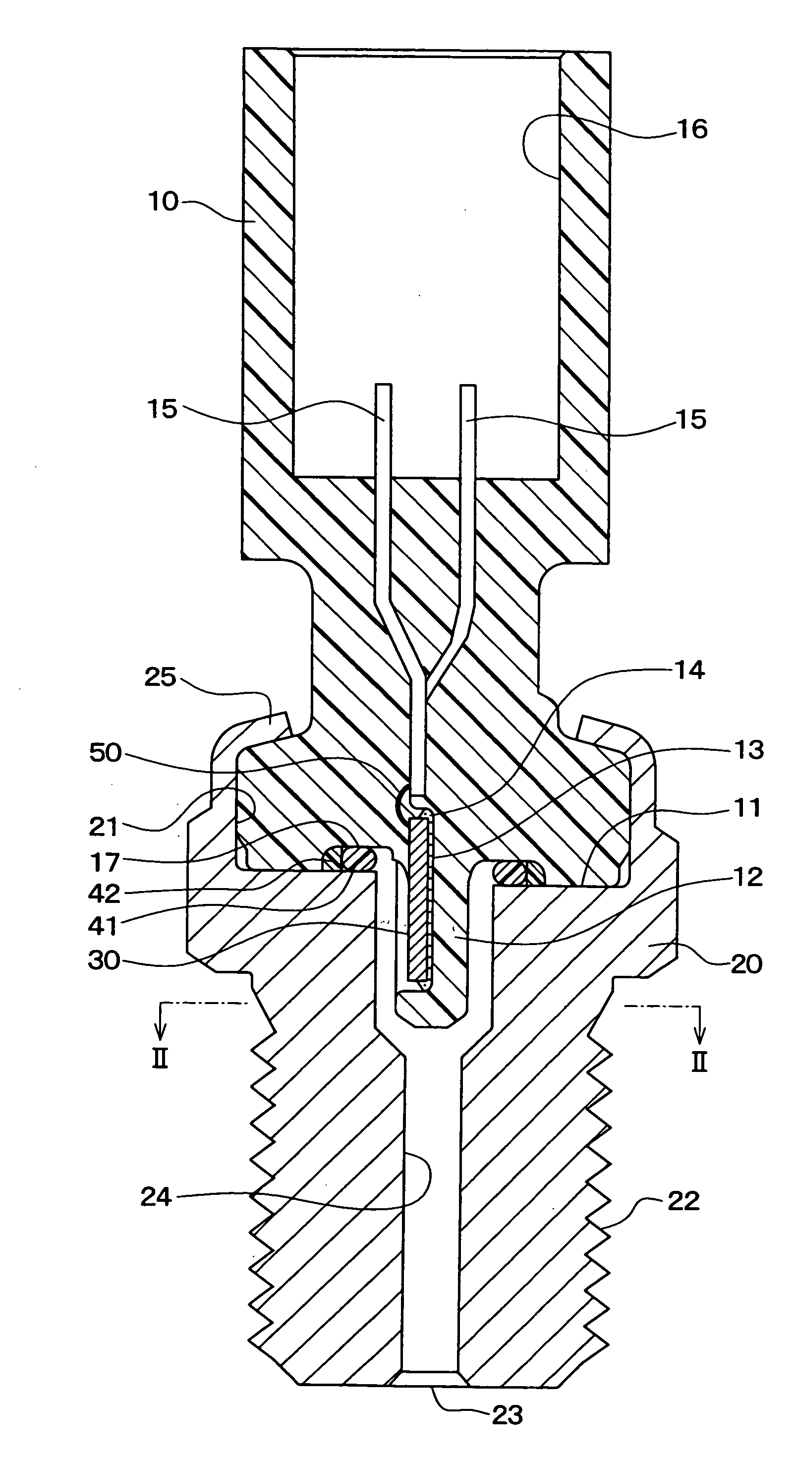
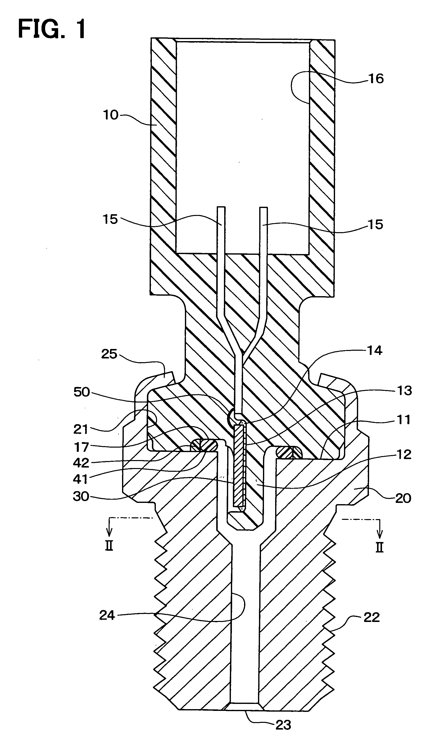
[0117]In this embodiment, only parts different from those in the first embodiment will be described. In the first embodiment, the connector case 10 and the housing 20 are sealed by the O ring 41 or the like, but this embodiment is characterized by employing a gasket.
[0118]FIG. 4 is a schematic sectional view of a pressure sensor according to a second embodiment of the present disclosure. As shown in this drawing, the groove 17 shown in FIG. 1 is not formed on the tip plane 11 of the connector case 10 but the tip plane 11 is formed in an end plane. Moreover, a metal gasket 43 is arranged on the other end side of the housing 20, that is, between the end on the receiving and depressed portion 13 side of the housing 20 and the connector 10.
[0119]The one end portion of the connector case 10 is inserted into a receiving and depressed portion 21 of the housing 20, and the end portion of the housing 20 is crimped on the one end portion of the connector 10 to form the crimp portion 25. With ...
third embodiment
[0121]In this embodiment, only parts different from those in the second embodiment will be described. FIG. 5 is a schematic sectional view of a pressure sensor according to a third embodiment of the present disclosure. As shown in this drawing, a tapered plane 26 is formed on the opening portion on the other end side of the housing 20 of the pressure introduction port 24 formed in the housing 20.
[0122]According to this, when the one end portion of the connector 10 is inserted into the depressed portion 13 as the receiving and depressed portion of the housing 30, the protruding portion 12 protruding from the tip plane 11 of the connector case 10 can be inserted into the pressure introduction port 24 while sliding on the tapered plane 26. Thus, the connector case 10 can be easily mounted in the housing 20.
[0123]The tapered plane 26 of the housing 20 can be also employed for the housing 20 according to the first embodiment.
fourth embodiment
[0124]In this embodiment, only parts different from those in the first embodiment will be described. FIG. 6 is a schematic sectional view of a pressure sensor according to a fourth embodiment of the present disclosure. As shown in this drawing, the groove 17 shown in FIG. 1 is not formed on the tip plane 11 of the connector case 10 but the tip plane 11 is formed in a flat plane. Moreover, the protruding portion 12 protruding from the tip plane 11 of the connector case 10 has the backup ring 42 and the O ring 41 arranged thereon in this order from the tip plane 11 side. In other words, the backup ring 42 and the O ring 41 are arranged between the side surface of the protruding portion 12 and the wall surface of the pressure introduction port 24.
[0125]According to this, the backup ring 42 and the O ring 41 can seal a shaft and hence the size of the pressure sensor can be further reduced. Moreover, since the backup ring 42 and the O ring 41 are arranged in the introduction direction of...
PUM
 Abstract
Description
Claims
Application Information
 - R&D
- Intellectual Property
- Life Sciences
- Materials
- Tech Scout
- Unparalleled Data Quality
- Higher Quality Content
- 60% Fewer Hallucinations
Browse by: Latest US Patents, China's latest patents, Technical Efficacy Thesaurus, Application Domain, Technology Topic, Popular Technical Reports.
© 2025 PatSnap. All rights reserved.Legal|Privacy policy|Modern Slavery Act Transparency Statement|Sitemap|About US| Contact US: help@patsnap.com


