Air purification system, method for purifying air inside a structure

Inactive Publication Date: 2009-02-26
KONINKLIJKE PHILIPS ELECTRONICS NV
View PDF12 Cites 7 Cited by
  • Summary
  • Abstract
  • Description
  • Claims
  • Application Information

AI Technical Summary

Benefits of technology

[0014]According to the invention, a method for purifying air in a structure using an air purification system according to claim 1, comprises the following steps: providing the air purification system inside a structure, adjusting the distance between the air purification system and a ceiling of the structure in order to position the imaginary horizontal plane at eye level of a human being or higher, adjusting the second screen with respect to the first radiation source in order to direct a beam of UV radiation generated by the first radiation source towards a ceiling and/or at least one wall of the structure, and the beam of UV radiation having a angle α with the imaginary horizontal plane such that the UV rays reflect at least two times with the ceiling and/or the at least one wall before being radiated towards the space below the imaginary horizontal plane. This method allows purification of the air inside the structure without exposing the human beings inside the structure to an unacceptable level of UV-B and/or UV-C radiation.
[0015]Another preferred embodiment of the method for purifying air in a structure is characterized in that in the step of adjusting the second screen with respect to the first radiation source, the beam of UV radiation has an angle α with the imaginary horizontal plane such that the UV rays reflect at least a first time with the at least one wall and at least a second time with the ceiling

Problems solved by technology

It is a disadvantage of the air purifier according to the prior art that human beings present

Method used


Image

  • Air purification system, method for purifying air inside a structure
  • Air purification system, method for purifying air inside a structure
  • Air purification system, method for purifying air inside a structure

Examples


Embodiment Construction

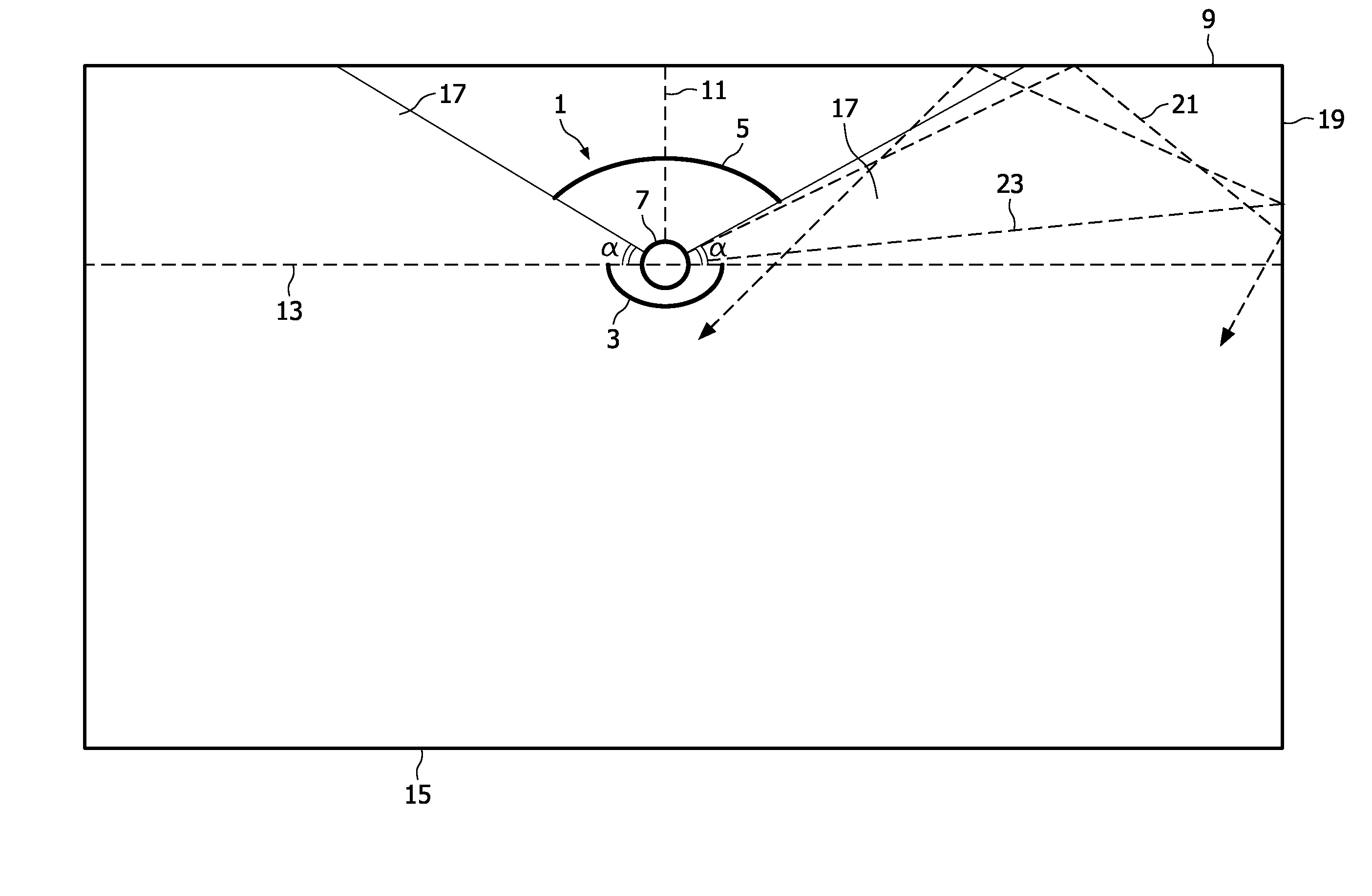
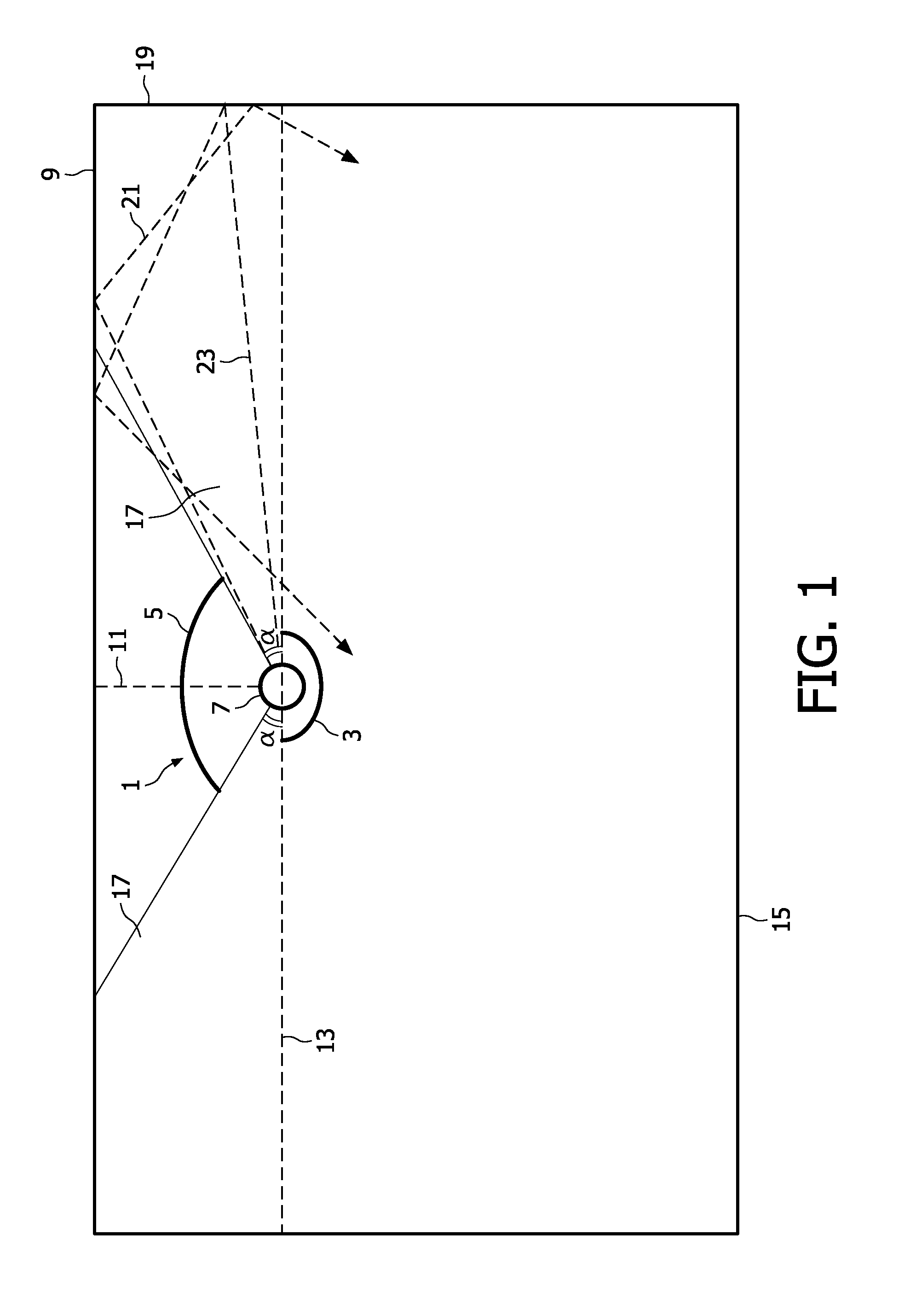
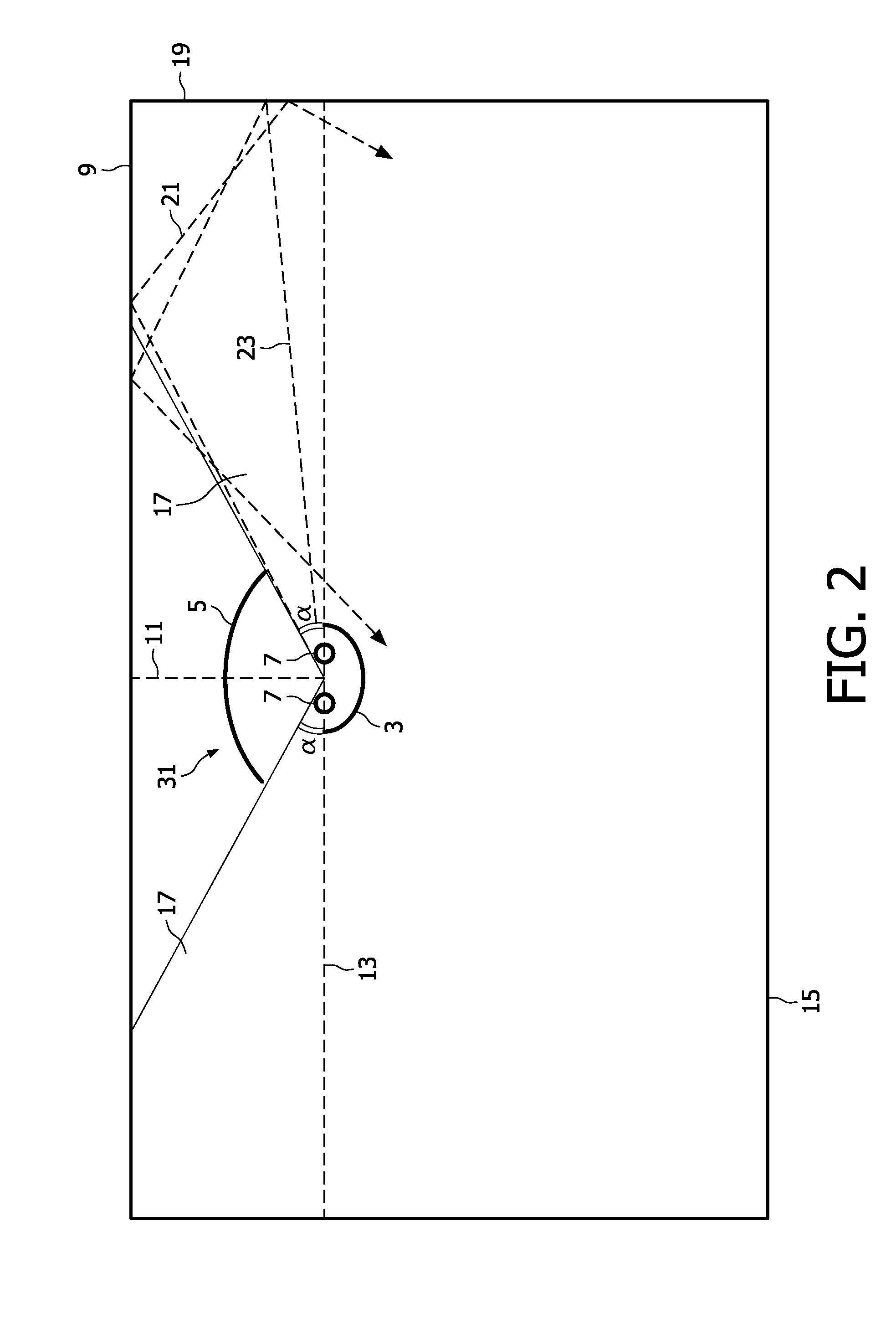
[0027]Referring to FIG. 1, a cross-sectional and schematic drawing of an embodiment of an air purification system 1 according to the invention is shown. The air purification system 1 comprises a lower screen 3, an upper screen 5 and a radiation source 7 for generating UV-C radiation, i.e. radiation in a wavelength range of 280 nm to 200 nm or less. In an alternative embodiment, the radiation source 7 is arranged for generating UV-B radiation, i.e. radiation in a wavelength range of 280-320 nm. In a further alternative embodiment, the radiation source 7 is arranged for generating both UV-B and UV-C radiation. The air purification system 1 is suspended from the ceiling 9 of a structure, for example a hospital room, conference room, or a class room, to name a few. The lower screen 3, upper screen 5 and radiation source 7 are coupled to each other in a way known to the person skilled in the art to form a robust device, and the upper screen 5 is movable with respect to the radiation 7 al...


PUM

PropertyMeasurementUnit
Shapeaaaaaaaaaa
Luminescenceaaaaaaaaaa

Abstract

The invention relates to an air purification system for a structure comprising a first radiation source (7) for generating UV-B and/or UV-C radiation and having an imaginary horizontal plane (13) intersecting with the centre of the first radiation source (7), a first screen (3) facing the first radiation source (7) for preventing UV radiation generated by the first radiation source (7) from radiating directly outward from the air purification system (1, 31, 35, 41) into a space below the imaginary horizontal plane (13), a second screen (5) facing the first radiation source (7) as well as the first screen (5), adjustable with respect to the first radiation source (7) and at least partially coated with a photo-catalytic material at a surface facing the first radiation source (7). The invention further relates to a method for purifying air inside a structure using such an air purification system.

Description

TECHNICAL FIELD[0001]The invention relates to an air purification system for a structure. The invention further related to a method for purifying air inside a structure using such a system.BACKGROUND[0002]Air disinfection systems using germicidal UV radiation, usually in the form of UV-C radiation, are known as such. The germicidal UV radiation disinfects the air by damaging DNA which will inactivate for example, viruses, bacteria, molds, and yeast that are present in the air. Such air disinfection systems are particularly used in places where relatively many people are present for a longer time, for example in office buildings, schools, waiting rooms in hospitals and in places where there is a high risk for infection by air transmittable diseases such as isolation rooms in hospitals, shelters for homeless people, TBC clinics etc. UV based air purification systems use a layer of a photo-catalytic material that is irradiated by a UV radiation source to produce hydroxyl radicals that ...

Claims


Application Information

Patent Timeline
IPC IPC(8): B03C3/016B03C3/38
CPCA61L9/205B01D53/007B01D53/885B01D2255/802B01D2259/802H01J61/35F21V7/0008F21V33/00F21Y2113/00F21Y2113/02F21S8/04F21Y2113/20
Inventor LEROUX, ALAIN LOUIS CLAUDEGEBOERS, JACQUES MARIA JOZEF
Owner KONINKLIJKE PHILIPS ELECTRONICS NV
Why Eureka
Try Eureka