
Irrigation control system

Active Publication Date: 2009-02-26
NETAFIM LTD +1
View PDF11 Cites 9 Cited by
  • Summary
  • Abstract
  • Description
  • Claims
  • Application Information

AI Technical Summary

Benefits of technology

[0014]In an embodiment of the invention, because the sealing septum substantially provides appropriate sealing of the water reservoir, the porous material of the hydraulic coupler is generally not required when wet to have a bubbling pressure greater than an absolute value of a minimum matric potential of the soil in which the tensiometer is to be used. (As noted above, matric potential is usually a negative pressure, and a minimum matric potential is negative pressure having a greatest absolute value. Bubbling pressure of a material is the negative of a minimum matric potential at which air will not pass through the material, generally when the material is properly wetted.) By substantially separating the function of providing hydraulic contact with a soil and the function of sealing against passage of air, a relatively broad spectrum of materials can be used for the hydraulic coupler and a tensiometer can advantageously be configured for specific agricultural applications while also providing relatively improved hydraulic contact with the soil.
[0016]It is noted that the roots of many plants are able to generate hydraulic pressure equivalent to about 15 atmospheres in order to extract water from soil. Such pressure can cause relatively steep gradients in soil moisture for which soil in a near neighborhood of a plant's roots is substantially drier than soil outside of the near neighborhood. Since plant growth and health are generally relatively sensitive to the soil environment near to their roots, a tensiometer for which plant roots are able to grow inside the tensiometer's hydraulic coupler can provide water matric potential measurements advantageously sensitive to soil conditions in the near neighborhoods of plant roots. Such measurements can be particularly advantageous for use in controlling an irrigation system that provides water to the plants.
[0017]An aspect of some embodiments of the invention relates to providing a tensiometer that is relatively inexpensive and simple to make and use.

Problems solved by technology

As matric potential of a soil increases, the more difficult it is for plants to extract water from the soil.
When soil gets so dry that plants cannot extract water from the soil, plant transpiration stops and plants wilt.
Whereas such contact can usually be provided by a surface of a ceramic, for coarse soils or gravels, such mechanical and resulting hydraulic contact can be difficult to obtain using a ceramic material.

Method used


Image

  • Irrigation control system
  • Irrigation control system
  • Irrigation control system

Examples


Embodiment Construction

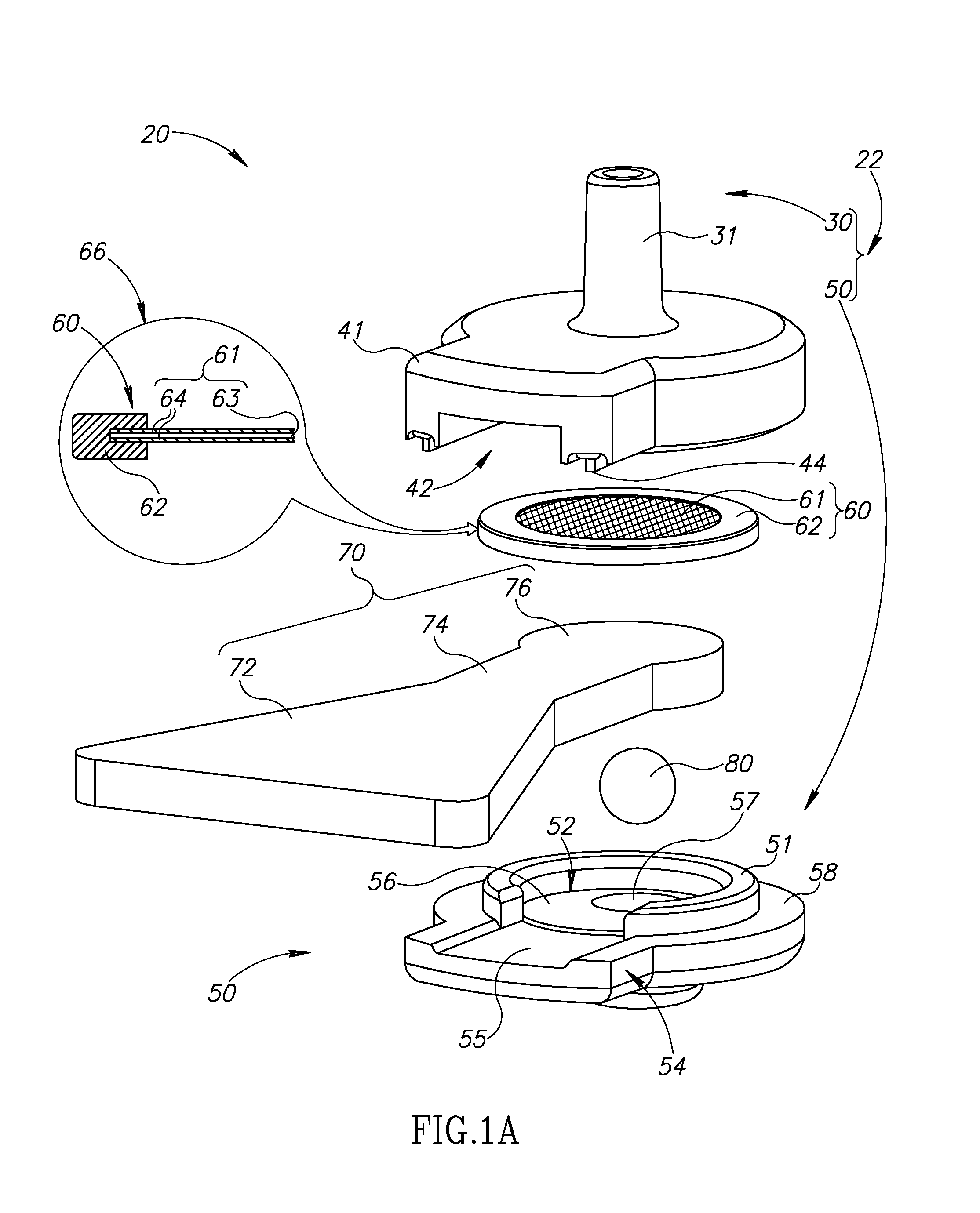
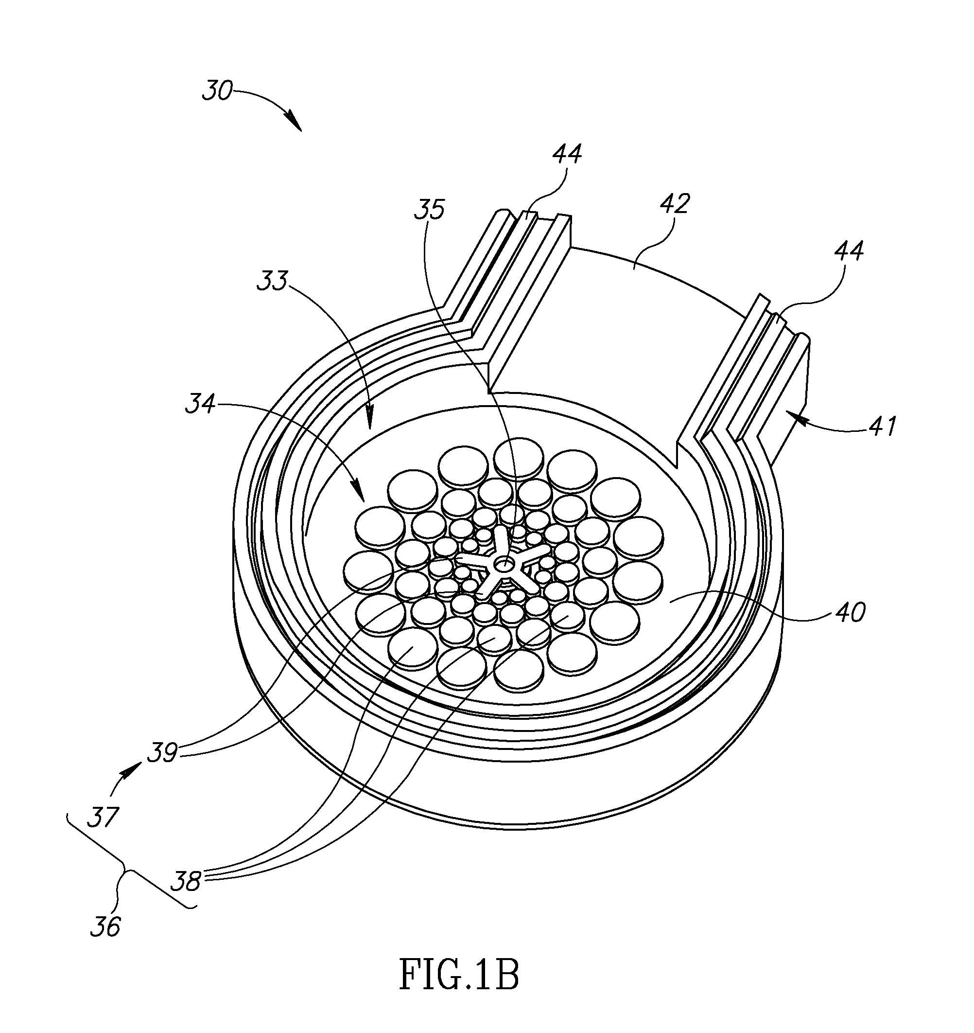
[0053]FIG. 1A schematically shows an exploded view of a tensiometer 20 for measuring water matric potential in a soil, in accordance with an embodiment of the invention. FIGS. 1B-1D schematically show enlarged views of components of tensiometer 20 shown in FIG. 1A. FIG. 2 schematically shows an assembled view of tensiometer 20. For convenience of presentation, apparatus 20 is referred to as a tensiometer, even though, as shown in FIGS. 1A-1D, it optionally, does not comprise a water reservoir and apparatus for providing a measure of pressure in the reservoir.

[0054]Tensiometer 20 optionally comprises a housing 22 having first and second housing parts 30 and 50, hereinafter referred to for convenience as housing top 30 and housing bottom 50, a sealing septum 60, a hydraulic soil coupler 70 formed from a porous material and a resilient element 80.

[0055]Hydraulic coupler 70 is formed having a soil-coupling region 72 that extends outside of housing 22 when tensiometer 20 is assembled (FI...


PUM


Abstract

A tensiometer for use in determining matric potential of a soil comprising: a water inlet; a hydraulic coupler comprising a porous material for providing hydraulic coupling between water that enters the inlet and the soil; and a septum that seals water that enters the inlet against ingress of air via the porous material.

Description

RELATED APPLICATIONS[0001]The present application claims the benefit under 35 U.S.C. 119(e) of U.S. Provisional Application 60 / 935,571 filed Aug. 20, 2007, the disclosure of which is incorporated herein by reference.FIELD[0002]The invention relates to systems and apparatus for controlling irrigation systems.BACKGROUND OF THE INVENTION[0003]Irrigation systems that deliver water, often containing plant nutrients, pesticides and / or medications, to plants via networks of irrigation pipes are very well known. In some irrigation systems, external sprinklers, emitters or drippers, are connected to the irrigation pipes to divert water from the pipes and deliver the water to plants. In many such irrigation networks, water from the pipes is delivered to the plants by emitters or drippers that are installed on or “integrated” inside the irrigation pipes. For convenience, any of the various types of devices used in an irrigation system to divert water from an irrigation pipe in the system and d...

Claims


Application Information

Patent Timeline
IPC IPC(8): A01G25/16G01N5/02F16K17/36
CPCG01N7/10A01G25/167Y10T137/189Y10T137/0318Y02A40/22
Inventor SHANI, URISCHWEITZER, ABRAHAM
Owner NETAFIM LTD
Learn More