Aircraft wing spoiler arrangement

Active Publication Date: 2009-02-26
AIRBUS OPERATIONS LTD
View PDF9 Cites 9 Cited by
  • Summary
  • Abstract
  • Description
  • Claims
  • Application Information

AI Technical Summary

Benefits of technology

[0019]The width of the gap may be adjustable in-flight, for instance by translating, expanding or rotating one or both of the spoilers. This enables the gap to be made relatively wide when the aircraft is flying at low speeds, and relatively narrow when the aircraft is flying at high speeds.

Problems solved by technology

Typically the width of the gap is sufficiently small to choke the flow of air through the gap such that for at least one flight regime with the adjacent spoilers deployed, they generate flow vortices and / or boundary layers which interfere with each other.

Method used


Image

  • Aircraft wing spoiler arrangement
  • Aircraft wing spoiler arrangement
  • Aircraft wing spoiler arrangement

Examples


Embodiment Construction

)

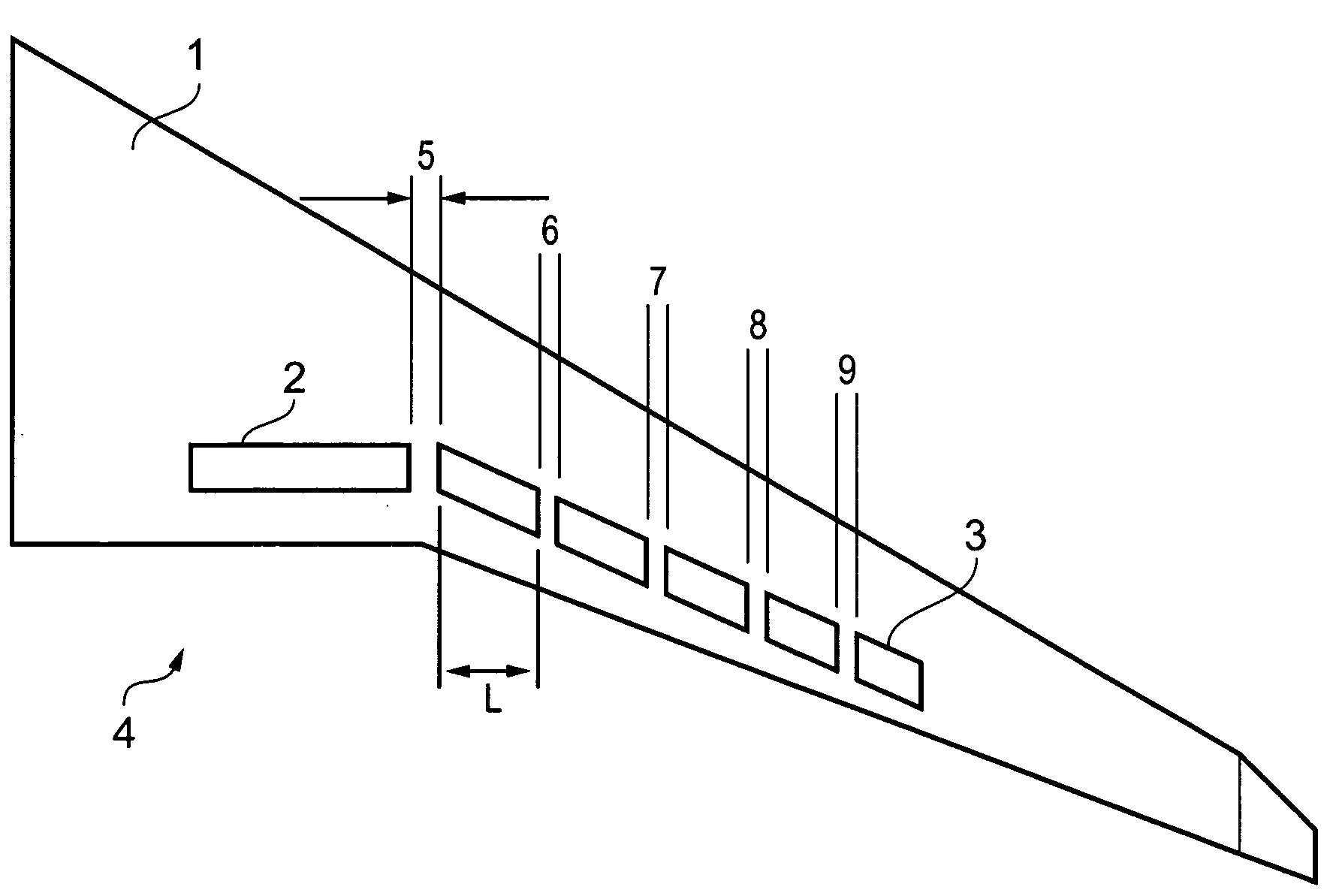
[0026]An aircraft wing shown in FIG. 1 has an upper surface 1; and a line of spoilers including a relatively large inboard spoiler 2 (oriented at right angles to the aircraft's direction of flight 4) and four relatively small outboard spoilers 3 (which are swept back relative to the aircraft's direction of flight 4).

[0027]The spoilers 2,3 are pivotally attached to the upper surface 1, and each is controlled by an independent actuator which can pivot the spoiler up into a deployed position, and down into an inoperative position in which the spoiler lies flush with the upper surface 1.

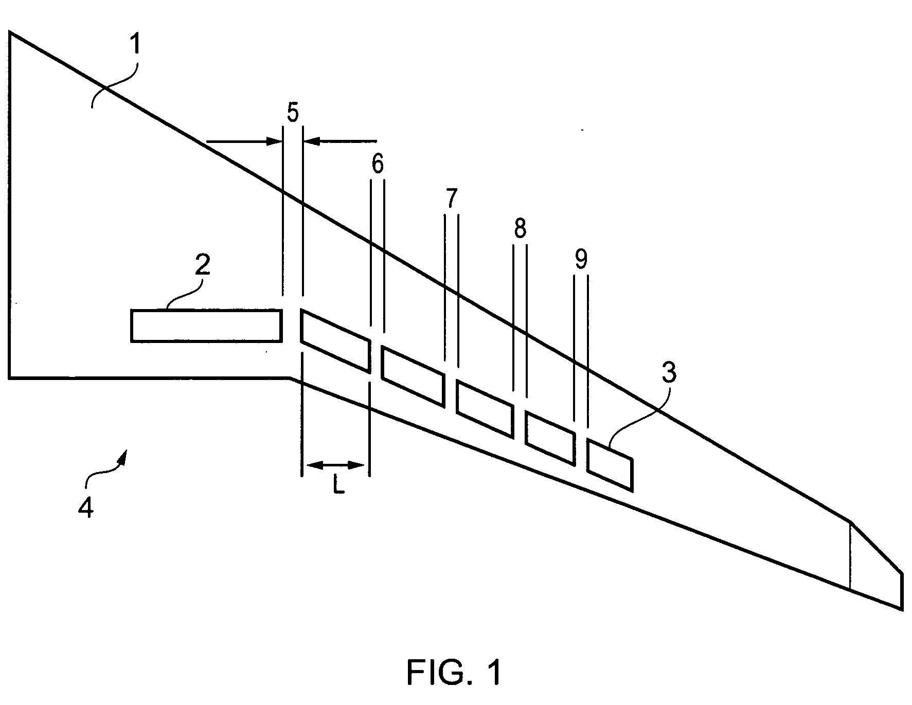
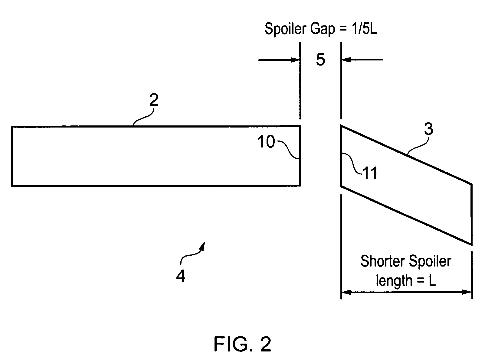
[0028]The spoilers 2,3 include rubber seals along their edges which seal with complimentary rubber seals in the upper surface of the wing when the spoilers are retracted. When the spoilers are deployed, then air gaps 5-9 open up between the adjacent spoilers. As shown in detail in FIG. 2, the smaller spoilers 3 have a projected length L when viewed in the direction of flight 4 of the aircraft, and the w...


PUM


Abstract

An aircraft wing comprising an upper surface; and two or more spoilers pivotally attached to the upper surface, wherein at least two adjacent ones of the spoilers are separated by a gap, and wherein the width of the gap is: greater than 1 cm; and sufficiently small to choke the flow of air through the gap such that for at least one flight regime with the adjacent spoilers deployed, the average air flow speed through the gap is less than 10% of the true air speed.
The reduced size of the spoilers reduces the spanwise wing loading and the spoiler hinge moment, whilst providing a net aerodynamic effect (in terms of destroying lift over the wing) similar to that of a conventional spoiler array with no gaps.

Description

FIELD OF THE INVENTION[0001]The present invention relates to an aircraft wing incorporating a novel spoiler arrangement.BACKGROUND OF THE INVENTION[0002]A spoiler is a panel hinged to the upper surface of a wing. The primary function of the spoiler is to reduce lift of the wing, although a secondary effect of the spoiler is to slightly increase the drag of the wing due to the increase in frontal area presented by the spoiler. The spoiler may be deployed during cruise, during landing approach, and / or during landing.[0003]Conventionally an array of such spoilers is provided for failsafe purposes. That is, each spoiler is controlled by an independent actuator so that if one of the actuators fails the remaining spoilers can still be deployed. The individual spoilers are closely spaced with no gap between the spoilers. Generally, spoilers are made from solid material such as metal or composite. The edges of the spoilers include solid rubber seals which prevent the leakage of airflow betw...

Claims


Application Information

Patent Timeline
Patent Type & Authority Applications(United States)
IPC IPC(8): B64C3/58
CPCB64C3/58
Inventor MATSUDA, YUKITAKA
Owner AIRBUS OPERATIONS LTD
Why Eureka
Try Eureka