Vehicle seat and vehicle seat evaluation method

a vehicle seat and seat technology, applied in the field of vehicle seats, can solve the problems of large influence of vibration inputted via members arranged below the ischial tuberosities, and achieve the effects of damping low frequency vibration, high linearity, and difference in ease of transmission

Active Publication Date: 2009-02-26
DELTA TOOLING CO LTD
View PDF8 Cites 13 Cited by
  • Summary
  • Abstract
  • Description
  • Claims
  • Application Information

AI Technical Summary

Benefits of technology

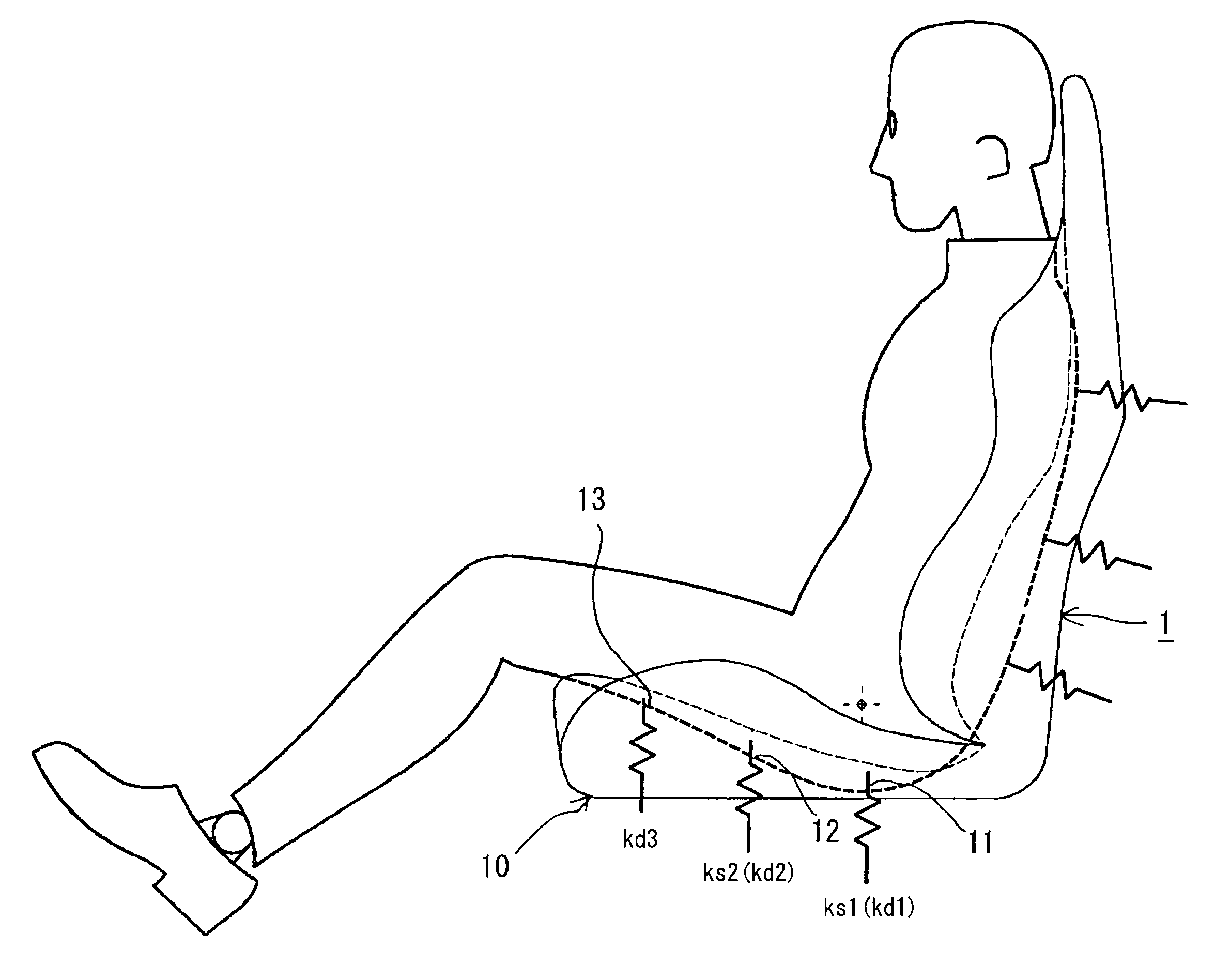
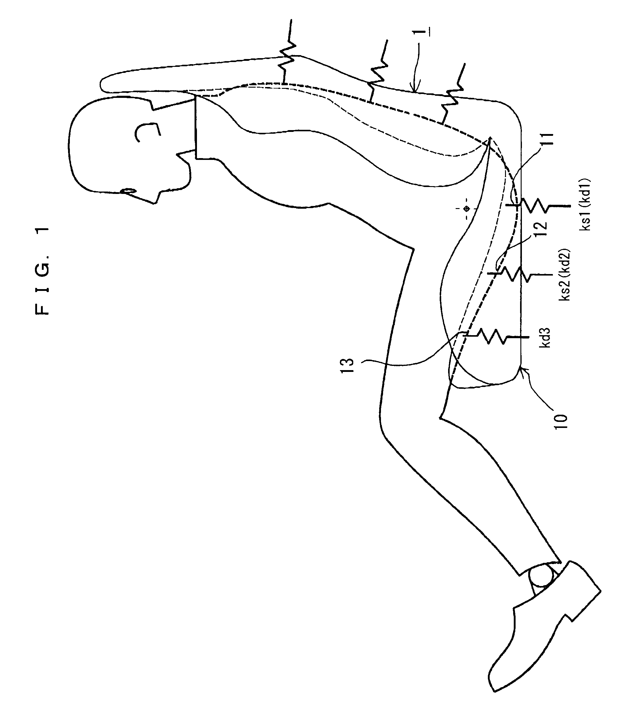
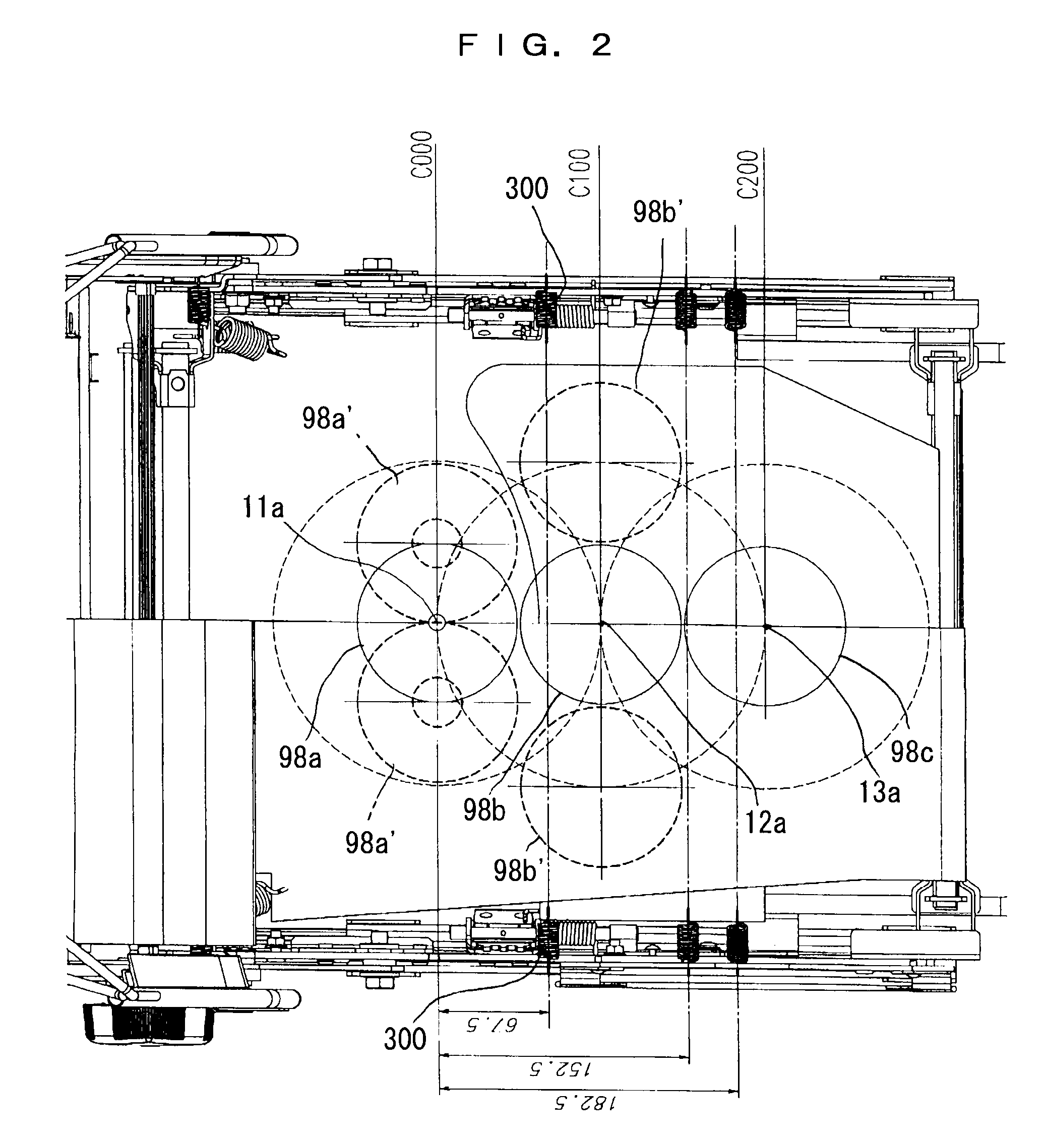
[0055]A vehicle seat according to the present invention includes a plurality of spring members and a seat cushion supporting a human body by operation of the spring members, and in the vehicle seat, when a first human body support portion having a center at a position corresponding to a substantially center between the pair of ischial tuberosities of a human body in the seat cushion, and a second human body support portion having a center at a position located forward at a horizontal distance of 100 millimeters along a longitudinally center line of the seat cushion from the first human body support portion are regarded respectively as spring elements made by operation of the plurality of spring members, a dynamic spring constant kd1 of the first human body support portion and a dynamic spring constant kd2 of the second human body support portion have a relationship of kd1<kd2 under the vibration condition such that excitation force thereof is substantially equal to excitation force working on each of the first human body support portion and the second human body support portion due to input vibration in a state that a person is seated and are set so that the second human body support portion becomes a fulcrum of motion during vibration damping operation. Accordingly, when excitation force of input vibration changes, a spring member that functions dominantly thereby switches in the plurality of spring members, and the dynamic spring constants kd1, kd2 change.
[0056]Concretely, the plurality of spring members are structured including a spring member, such as an outer layer member or a flat support member, which works when pressed in a thickness direction when coming into contact with a human body and has a quite soft, static spring constant, that is a so-called “zero spring characteristic”, a characteristic such that there is almost no increase in load in a certain bending range and the static spring constant does not change substantially in the range (hereinafter called “shallow-layer spring member”), a spring member which has high linearity and functions mainly when making the dynamic spring constant of the second human body support portion (hereinafter called “middle-layer spring member”), and a spring member which exhibits, together with spring force, damping force by a phase difference in a gravitational direction and in an anti-gravitational direction and functions mainly when making the dynamic spring constant of the first human body support portion (hereinafter called “deep-layer spring member”).
[0057]Specifically, when vibration is inputted, there is a difference in easiness of transmitting vibration between the portion where the pelvis including ischial tuberosities having bone projections is located and the portion where the femurs covered by muscle are located, depending on inherent vibration frequencies of respective portions of a human body. Specifically, input vibration at a low frequency with a large displacement amount becomes vibration shaking the entire trunk, and hence the first human body support portion as a spring element located below the ischial tuberosities just under the barycenter and having a low dynamic spring constant mainly operates to damp the low frequency vibration. That is, elasticity of the spring member determining the dynamic spring constant kd1 of the first human body support portion supporting a portion below the ischial tuberosities mainly operates to damp such low frequency vibration. On the other hand, when high frequency vibration with a small displacement amount is inputted, the human body support portion supporting from the femoral bases to substantially center portions of femurs (or the vicinities of the backs of knees) can easily be influenced by vibration. Further, since the load mass is smaller than the first human body support portion supporting the portion below the ischial tuberosities, the dynamic spring constant kd2 (and kd3) including viscous damping and Coulomb friction force is not influenced by the deep-layer spring member that dominantly functions when making the dynamic spring constant kd1 of the human body support portion supporting the portion below the ischial tuberosities, and with the middle-layer spring member operating dominantly, it becomes higher than the dynamic spring constant kd1. Then, in the human body support portion supporting from the vicinities of femurs to substantially middle portions of femurs (or the vicinities of the backs of knees), the middle layer spring member and the shallow layer spring member operate dominantly, and the vicinities of femurs are supported by the dynamic spring constants kd2, kd3. Therefore, as compared to a conventional structure in which the dynamic spring constant of the human body support portion under the femurs is smaller than the dynamic spring constant of the human body support portion for the ischial tuberosities, the ratio of a shared load supported by the human body support portion as the spring element under the femurs becomes large. On the other hand, due to presence of support for the vicinities of femurs, sinking in the gravitational direction is limited particularly to a narrow range below the ischial tuberosities, not to the entire buttocks, and thus the ratio of shared loads supported by side frames becomes small, thereby alleviating the influence of high frequency vibration inputted to the side portions of femurs and / or the side portions of buttocks. Therefore, according to the present invention, the vibration absorption characteristic in a wide region from low frequency to high frequency is improved.
[0058]Further, in the vehicle seat of the present invention, when vibration is inputted during traveling, the entire femurs from the vicinities of femoral bases to the vicinities of the backs of knees are supported by the human body support portion with the dynamic spring constants kd2, kd3, backward tilting of the pelvis can be prevented. Since the dynamic spring constants kd2, kd3 operating dominantly on the femurs with small load masses have strong linearity and large restoring force, displacement in a pressing direction by vertical movement of the pelvic plane due to the motion of the lower limb when operating a pedal is suppressed small. Since the pedal operating motion is performed accompanying pivoting in the forward / backward direction of a front edge portion of the seat cushion, partial pressing on the backs of knees by bending of the front edge portion of the seat cushion is suppressed, and the influence on the muscle of femurs by seating pressure is alleviated, that is, bending of the muscle of the backs of knees becomes smaller, thereby decreasing the displacement amount due to pressing of muscle. Accordingly, when applied to a driver's seat, legs or femurs are allowed to move like sliding on the surface of the seat cushion, and thus the operability of pedals improves, thereby contributing to alleviation of fatigue.
[0059]Further, the static spring constant when applying pressure by a pressure board with a diameter of 200 mm on the first human body support portion corresponding to the portion under the ischial tuberosities is set to be larger than that of the second human body support portion. The size of the pressure board being the diameter of 200 mm causes that, besides operation of the spring member determining the spring characteristic of the first human body support portion corresponding to the portion below the ischial tuberosities, the spring member of the second human body support portion operates at a position corresponding to the vicinities of femoral bases, and the spring characteristic in the first human body support portion and the spring characteristic in the second human body support portion operate in parallel. Thus, ks1 becomes higher than ks2, and the portion below the ischial tuberosities can be supported adequately. Therefore, the present invention can realize a stable seating posture also in a static seating state.

Problems solved by technology

However, since the seat having such a structure has a large dynamic spring constant below the ischial tuberosities, it has a drawback in that the influence of vibration inputted via members (cushion member, frame member, and the like) arranged below the ischial tuberosities is large.

Method used


Image

  • Vehicle seat and vehicle seat evaluation method
  • Vehicle seat and vehicle seat evaluation method
  • Vehicle seat and vehicle seat evaluation method

Examples


example 1

[0160]As shown in FIG. 3, example 1 is constituted including a flat support member 20 strained in the forward / backward direction as the seat cushion 10. The flat support member 20 is disposed at the lowest layer in the cushion material constituting the seat cushion 10, and a three-dimensional knitted fabric, a two-dimensional woven fabric, or the like can be used. In this embodiment, a three-dimensional knitted fabric is used. A rear edge portion 21 of the flat support member 20 is supported by a plurality of coil springs 30 as rear spring members engaging with a rear end frame 10a of the seat cushion 10. The coil springs 30 are arranged at substantially equal intervals and substantially in parallel with each other. In this embodiment, four extension coil springs with a spring constant (static spring constant 0.4 kg / mm are used. Note that the three-dimensional knitted fabric (three-dimensional net member) is knitted by reciprocating a connecting thread between a pair of ground knitt...

example 2

[0173]As shown in FIG. 7 and FIG. 8, example 2 is structured having, similarly to the example 1, the auxiliary flat support member 40 at a lower layer of the flat support member 20 and in the range corresponding to the second human body support portion 12 and the third human body support portion 13. Further, in a rear portion of the seat cushion 10, there is disposed a torsion bar 10f, which is arranged along a width direction of the seat cushion. An arm member 10g is coupled to this torsion bar 10f, and a rear edge support frame 10h is coupled to this arm member 10g. Accordingly, the rear edge support frame 10h is supported swingably in the forward / backward direction by elasticity of the torsion bar 10f. Therefore, in this example, the torsion bar 10f functions as a rear spring member and constitutes a deep-layer spring member giving spring force and damping force. More specifically, the auxiliary flat support member 40 is provided so that a substantially middle portion of a rear e...

example 3

[0197]In Example 3, a structure having the dynamic spring constants of the present invention is realized in a structure in which a urethane member is mounted and used on a flat spring member, which is different from the structure in which a three-dimensional knitted fabric is provided by stretching as in the example 1 and the example 2.

[0198]Specifically, in this example, as shown in FIG. 62 and FIG. 63, a torsion bar 10k to be a deep-layer spring member is arranged as a rear spring member in the rear portion of the seat cushion 10, an arm member 10m which pivots downward about the torsion bar 10k from a substantially horizontal position in the drawing is provided, and a rear edge support frame 10n is coupled thereto. Then, with this rear edge support frame 10n, a urethane member 60 constituting a middle-layer spring member as well as a rear end of a flat spring member 50 are engaged and supported thereon. A front end of the flat spring member 50 is engaged with a fixing frame 10j l...


PUM


Abstract

A vehicle seat allowing to improve a vibration absorption characteristic, securing a stable seating posture, having high vehicle operability, and allowing to alleviate fatigue due to long time seating. In a seat cushion of a vehicle seat, a first human body support portion having a center at a position corresponding to a substantially center between the pair of ischial tuberosities of a human body, and a second human body support portion corresponding to the vicinities of femoral bases of a human body and having a center at a position located forward at a horizontal distance of 100 mm along a longitudinally center line of the seat cushion from the first human body support portion are regarded respectively as spring elements, and static spring constants and dynamic spring constants thereof are set to a predetermined relationship. Thus, stability and vibration absorbency during static seating are improved.

Description

TECHNICAL FIELD[0001]The present invention relates to a vehicle seat for automobiles, aircrafts, trains, ships, forklifts, and the like, and a vehicle seat evaluation method.BACKGROUND ART[0002]As a method of evaluating the performance of a seat, there are performed pressing a predetermined portion by a pressure board, obtaining a relationship between force (load) and a displacement (bending) at this moment, and thereby obtaining a spring constant (static spring constant) as an elasticity characteristic of the portion, or there are performed mounting a weight on a predetermined portion, applying vibration in a state of being stable by its own weight, drawing on a Lissajous figure a relationship between a load working on the weight (F=ma (m is mass of the weight, a is acceleration generated on the weight by vibration) and a relative displacement of the weight, and obtaining the static spring constant from inclination in the Lissajous figure. On the other hand, for evaluating vibratio...

Claims


Application Information

Patent Timeline
Patent Type & Authority Applications(United States)
IPC IPC(8): B60N2/44B60N2/70A47C7/35B60N2/90
CPCB60N2/7094B60N2/70A47C7/34B60N2/00B60N2/54
Inventor FUJITA, ETSUNORI
Owner DELTA TOOLING CO LTD
Why Eureka
Try Eureka