
Vehicle, control method thereof and braking device

a technology of braking device and control method, which is applied in the direction of electric devices, motor/generator/converter stoppers, propulsion using engine-driven generators, etc., can solve problems such as torque shock, and achieve the effect of increasing the kinetic energy of the vehicl

Active Publication Date: 2009-02-26
TOYOTA JIDOSHA KK
View PDF16 Cites 23 Cited by
  • Summary
  • Abstract
  • Description
  • Claims
  • Application Information

AI Technical Summary

Benefits of technology

[0005]A vehicle, a control method thereof and a braking device according to the present invention has an object to prevent occurrence of torque shock during braking. The vehicle, the control method thereof and the braking device according to the present invention has another object to allow smooth coordination between a braking force by a motor and a braking force by a machine brake. Further, the vehicle, the control method thereof and the braking device according to the present invention has a further object to increase energy efficiency by regeneration of a larger amount of kinetic energy to electric power during braking.
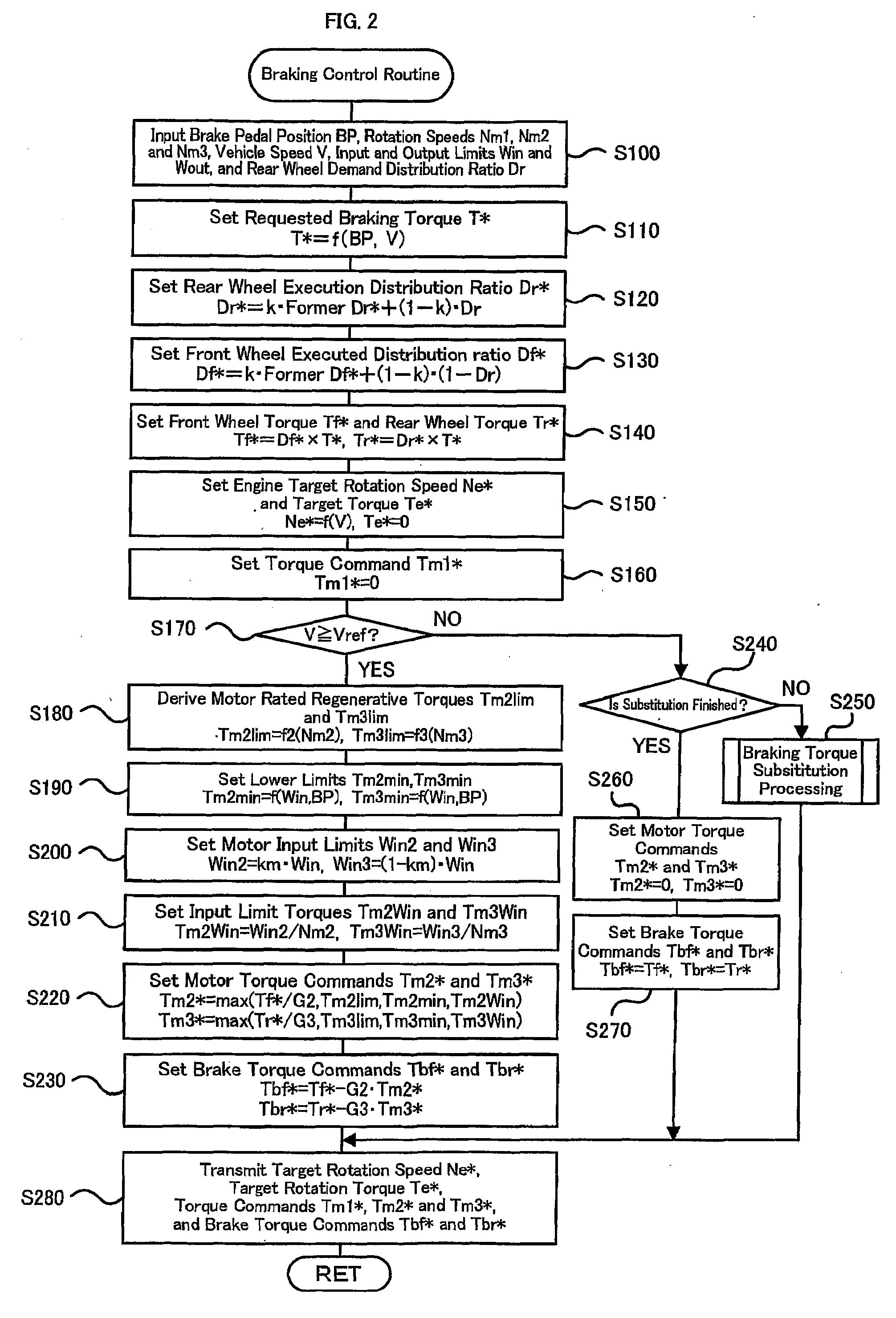
[0019]In another preferable embodiment of the control method of the vehicle, the control method includes the step of controlling the motor and the braking force application unit so that when the rotation speed of the motor is a predetermined rotation speed or higher, the regenerative torque is output from the motor within the range of the rated torque of the motor, an input limit torque based on the input limit, and the set lower limit regenerative torque, and the braking force according to the braking request is applied to the vehicle, and controlling the motor and the braking force application unit so that when the rotation speed of the motor is lower than the predetermined rotation speed, no regenerative torque is output from the motor, and the braking force according to the braking request is applied to the vehicle. This arrangement prevents the torque shock that may occur at the stop of the motor.

Problems solved by technology

At this time, if the torque command of the motor is set by the charging limit value only of the battery as in the above described vehicle, the motor is controlled to output a large regenerative torque because of a low rotation speed of the motor at a low vehicle speed, and hydraulic driving takes a certain time, thereby preventing smooth coordination between the braking force by the motor and the braking force by the machine brake, which may cause torque shock.

Method used


Image

  • Vehicle, control method thereof and braking device
  • Vehicle, control method thereof and braking device
  • Vehicle, control method thereof and braking device

Examples


Embodiment Construction

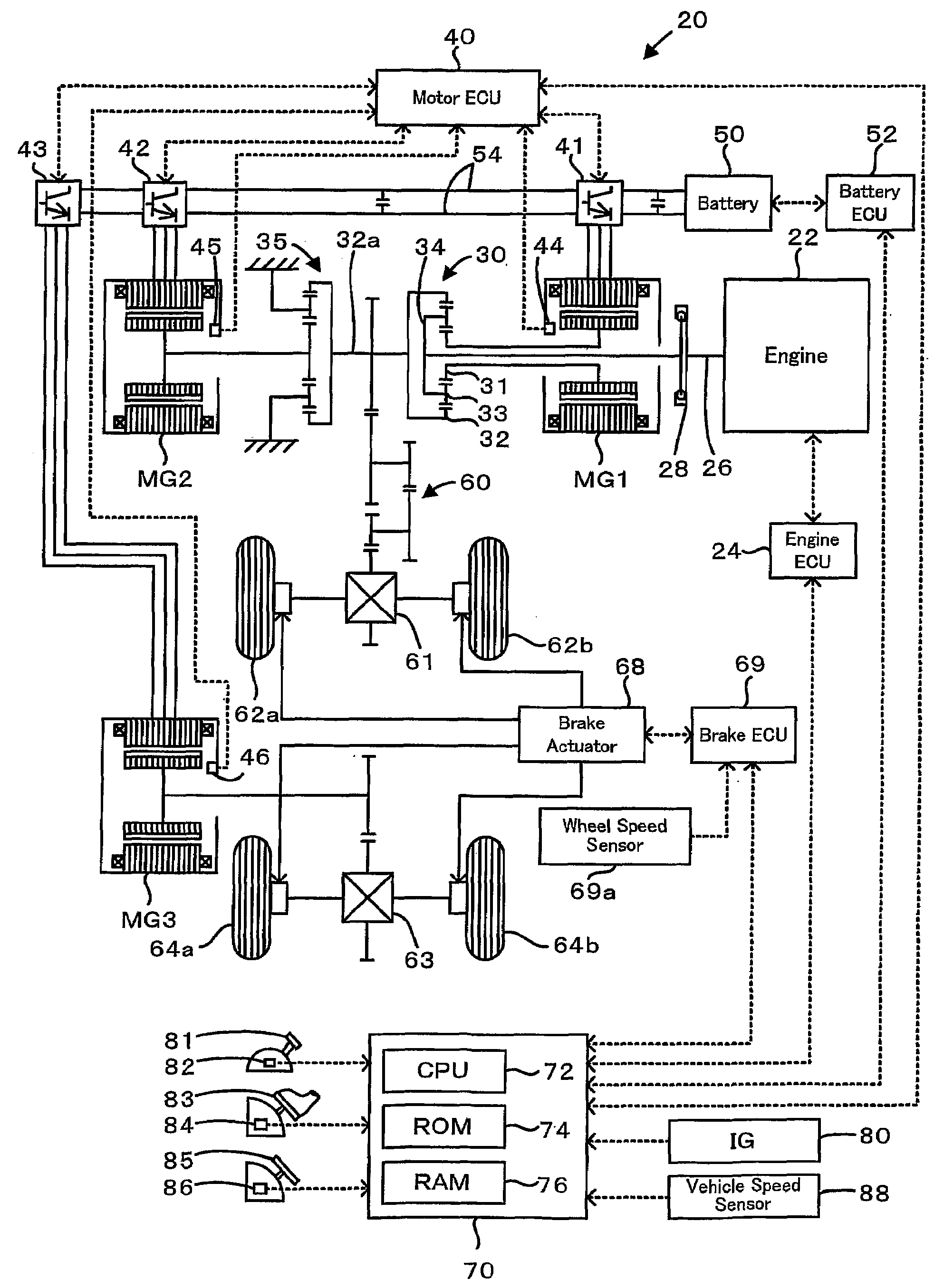
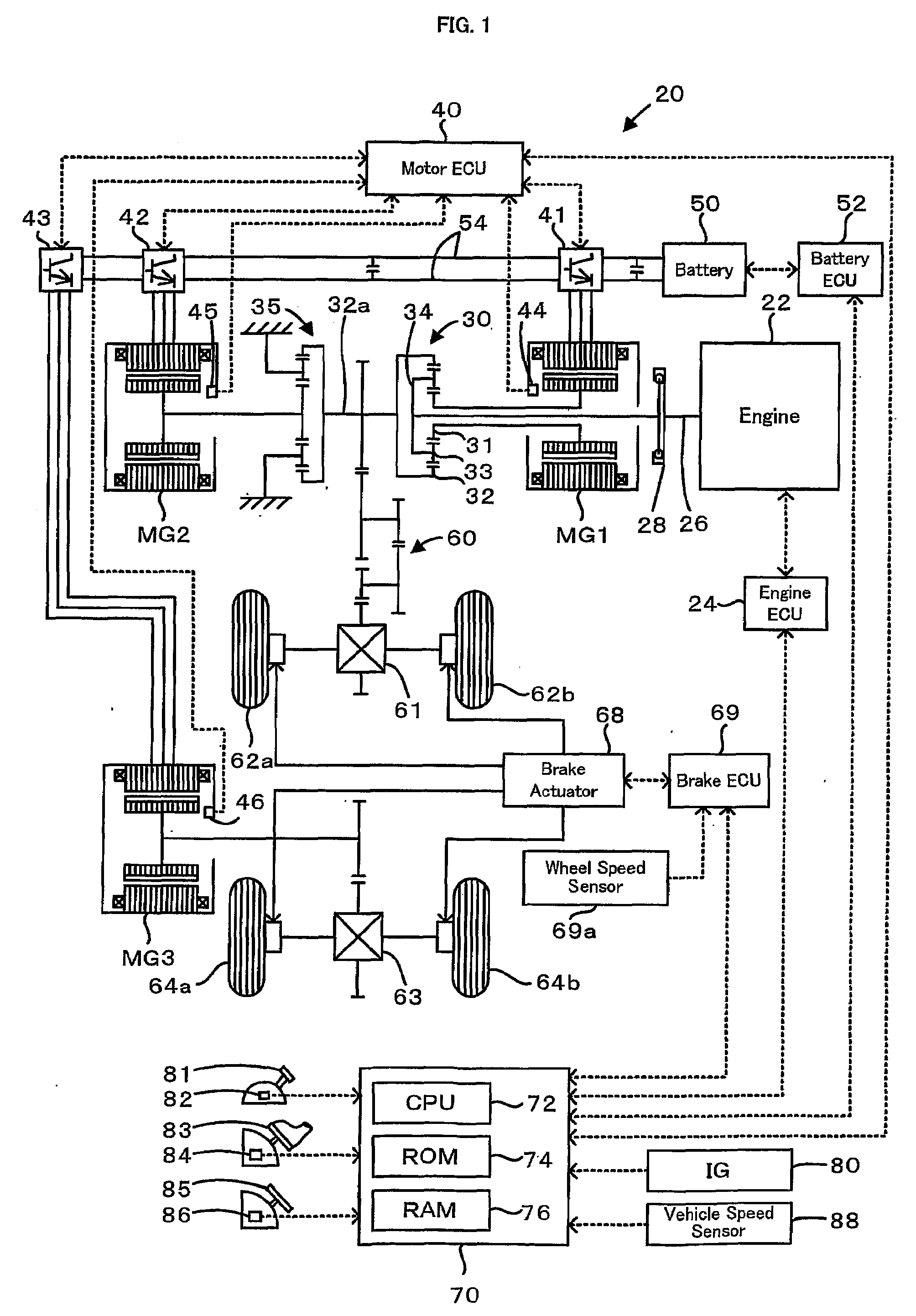
[0031]Next, the best mode for carrying out the invention will be described with reference to an embodiment. FIG. 1 schematically shows a configuration of a hybrid automobile 20 according to an embodiment of the present invention. As shown, the hybrid automobile 20 of the embodiment includes an engine 22, a three-shaft power distribution and integration mechanism 30 connected via a damper 28 to a crankshaft 26 as an output shaft of the engine 22, a motor MG1 that is connected to the power distribution and integration mechanism 30 and can generate electric power, a speed reduction gear 35 connected to the power distribution and integration mechanism 30 and connected to front wheels 62a and 62b via a gear mechanism 60 and a differential gear 61, a motor MG2 connected to the speed reduction gear 35, a motor MG3 connected to rear wheels 64a and 64b via a differential gear 63, and a hybrid electronic control unit 70 that controls the entire driving system of the vehicle.

[0032]The engine 2...


PUM


Abstract

During braking, lower limits are set based on an input limit of a battery and a brake pedal position, and the set lower limits limit regenerative torques output from motors. This prevents an output of an excessive braking force and torque shock caused by a hydraulic brake being not able to follow sudden changes in the regenerative torques output from the motors when the vehicle speed is reduced.

Description

TECHNICAL FIELD[0001]The present invention relates to a vehicle, a control method thereof and a braking device.BACKGROUND ART[0002]One proposed vehicle includes a front wheel motor MGf that can drive front wheels, a rear wheel motor MGr that can drive rear wheels, and a battery that can transfer electric power to and from the two motors MGf and MGr, and drives the two motors MGf and MGr within a range of a charging limit value of the battery when a braking force is requested (see, for example, Patent Document 1). In this vehicle, during braking, a torque command for regeneration of the rear wheel motor MGr that is low in driving frequency is first set within the range of the charging limit value of the battery, then a torque command for regeneration of the front wheel motor MGf is set under the limit using the set torque command of the rear wheel motor MGr and the charging limit value of the battery to perform regenerative control of the front wheel motor MGf and the rear wheel moto...

Claims


Application Information

Patent Timeline
IPC IPC(8): H02P3/14B60L7/24B60L7/10B60T8/17B60T8/26
CPCB60K6/445Y02T10/648B60K6/52B60L7/26B60L2240/423B60T1/10B60T13/586B60W10/08B60W10/184B60W10/26B60W20/00B60W30/18127B60W2540/12B60W2710/083Y02T10/6243Y02T10/6265Y02T10/6239B60L7/14B60L11/123B60L11/14B60L11/1861B60L15/2009B60L2210/40B60L2220/14B60L2240/12B60L2240/421B60L2240/441B60L2240/443B60L2240/461B60L2240/545B60L2240/547B60L2240/549B60L2250/26B60L2260/28B60L2270/145Y02T10/7077Y02T10/7044Y02T10/7005Y02T10/705Y02T10/7241Y02T10/7275Y02T10/6217B60K6/448B60L50/16B60L50/61B60L58/12Y02T10/62Y02T10/64Y02T10/70Y02T10/7072Y02T10/72B60W10/188B60W2510/083B60W2710/18B60W20/15
Inventor MUTA, KOICHIRO
Owner TOYOTA JIDOSHA KK
Learn More