3D fluid confined sample stream coulter flow cytometry

a flow cytometry and fluid confined technology, applied in the field of flow cytometry, can solve the problems of complex optical data generation, high cost, and limited cytometry devices, and achieve the effect of reducing the cost of cytometry, and improving the accuracy of flow cytometry

Inactive Publication Date: 2009-02-26
UNIV OF LOUISVILLE RES FOUND INC
View PDF16 Cites 25 Cited by
  • Summary
  • Abstract
  • Description
  • Claims
  • Application Information

AI Technical Summary

Problems solved by technology

However, current cytometry devices are confined to clinical and laboratory settings due to their size, expense, power requirements and need for skilled personnel.
Flow cytometry devices are optically based and require the sophisticated, bulky, and expensive equipment associated with optical detection and analysis.
One complexity associated with optical detection flow cytometry concerns the optical data that is generated by the technique.
Interpretation of this data is complicated, requiring skilled personnel and / or sophisticated analysis system
These devices remain, accordingly, bulky and expensive.
Portable technologies have advantages over optical detection flow cytometry, but portable technologies fail to provide the detection and analysis capabilities of optical detection flow cytometry.
Samples for many types of analysis require immediate processing and therefore cannot be analyzed by optical detection flow cytometry unless the sample is collected at the location of the flow cytometry device.
Using this approach, a cell or particle sample is suspended in a conductive solution, causing a spike in resistance between the electrodes when a low-conductivity object interrupts the electrical path.
However, this technique is only applicable to extremely well characterized and filtered sample solutions containing particles slightly smaller than the channel width.
Very small channel widths lead to the problems concerning blockage of the channel.
Consequently, the channel depth still limits sensitivity.
Other efforts to achieve three dimensional focusing in miniaturized optical detection systems have used complex structures that require alignment steps during fabrication, which are difficult to achieve in practice.
Electrical resistance (coulter) detection in cytometry remains limited to quantitative analysis, due to the fact that sensitivity remains insufficient for qualitative analyses including, for example, cell identification.

Method used


Image

  • 3D fluid confined sample stream coulter flow cytometry
  • 3D fluid confined sample stream coulter flow cytometry
  • 3D fluid confined sample stream coulter flow cytometry

Examples


Embodiment Construction

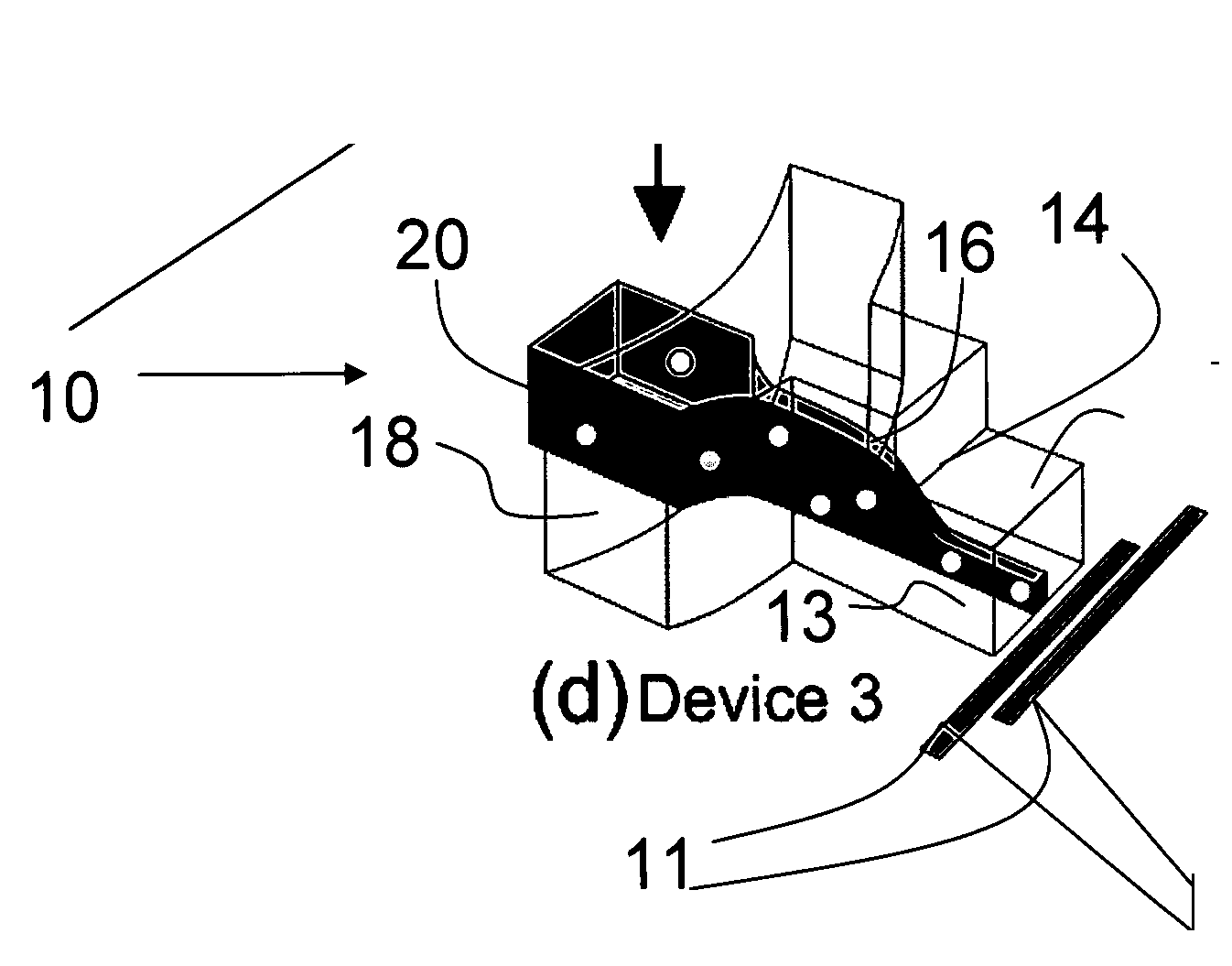
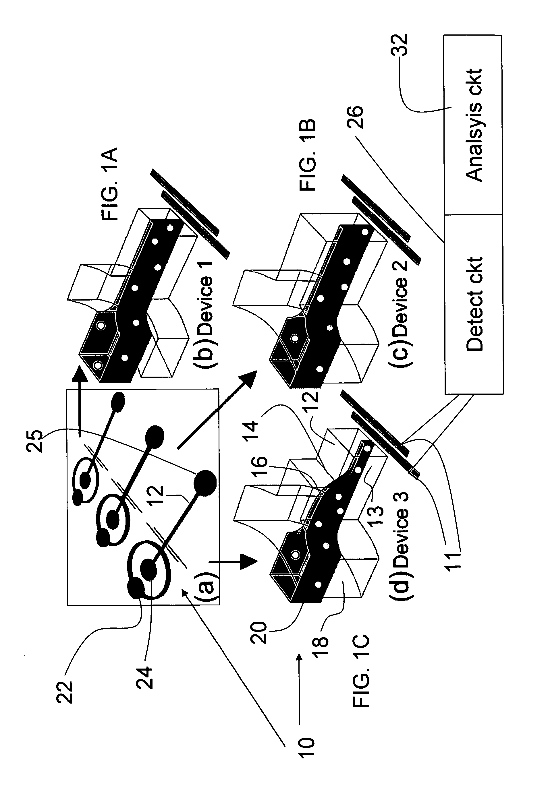
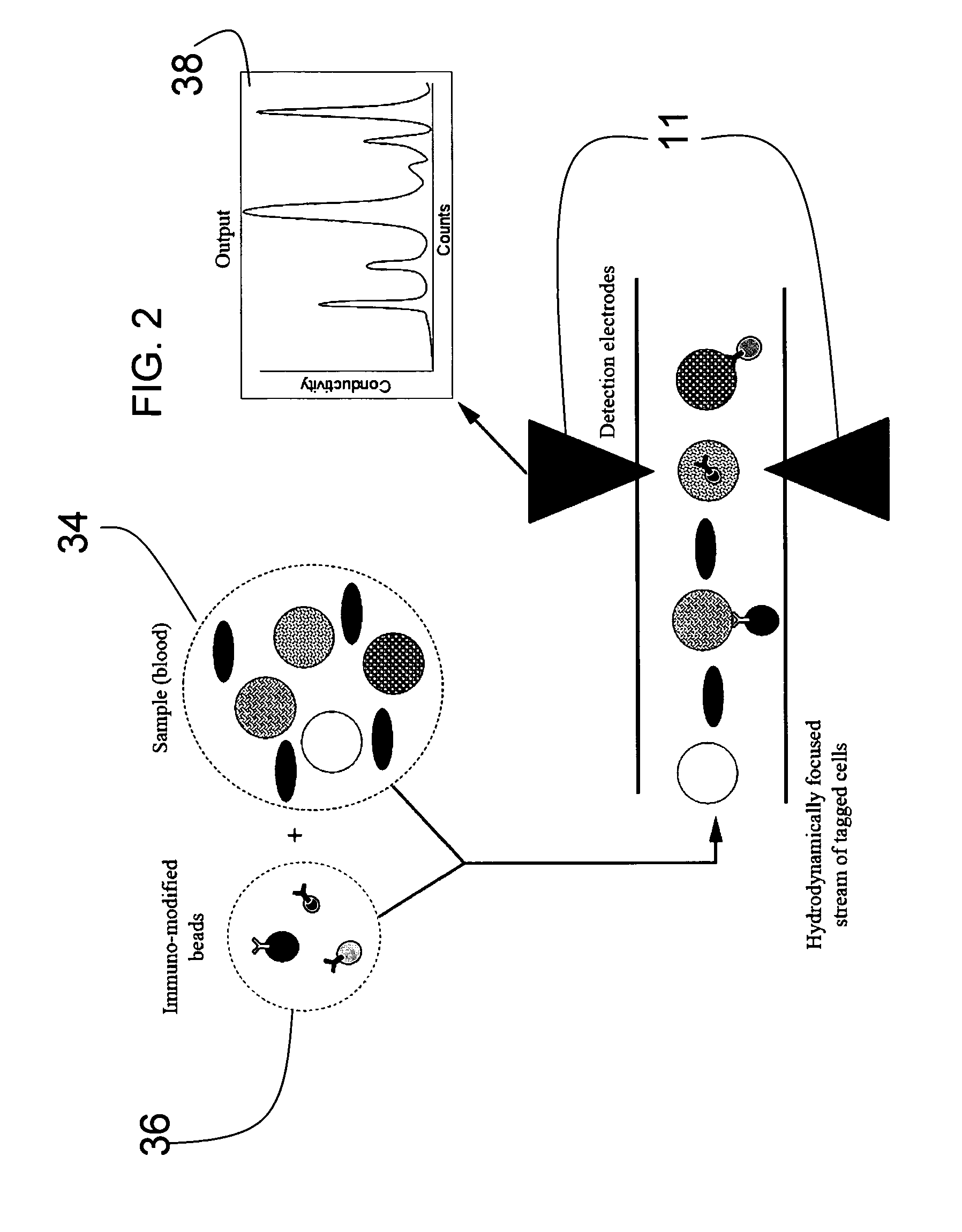
[0018]The invention provides quantitative and / or qualitative flow cytometry in a miniaturized three dimensional hydrodynamically focused micro fluidic device with an elastomer structure that can be readily fabricated by straightforward molding techniques. A sample stream in a device of the invention is confined in both the horizontal and vertical directions, and guided across sensing electrodes disposed transversely on the floor of a wide channel. Sensitivity surpasses two dimensional hydrodynamically confined microfluidic Coulter counters, while all channel dimensions in devices of the invention are substantially greater than the particle diameter. Vertical focusing is accomplished with a two-level design in micro channels, while the shape of the channels readily permits molding in a single cast elastomer piece.

[0019]A microfluidic flow cytometry device of an embodiment of the invention includes a substrate and transverse electrodes formed on the substrate. An elastomer microfluidi...


PUM

PropertyMeasurementUnit
widthaaaaaaaaaa
conductivityaaaaaaaaaa
concentrationaaaaaaaaaa

Abstract

A microfluidic flow cytometry device includes a substrate and transverse electrodes formed on the substrate. An elastomer microfluidic focusing channel system formed on the substrate focuses a sample stream onto the floor of an outlet channel that is substantially wider and taller than cells or particles of interest and that has the transverse electrodes disposed in its floor upstream of an exit site. A step in the outlet channel upstream of the transverse electrodes vertically confines sample stream flow onto the floor of the outlet channel over the transverse electrodes. Buffer inlet channels introduce a buffer stream for horizontal focusing of the sample stream into the central region of the outlet channel at the transverse electrodes. A sample inlet channel is smaller in vertical height than the buffer inlet channels for introducing a sample stream such that the buffer vertically focuses the sample stream away from the top of the outlet channel. Sensitivity of detection is good enough to conduct both qualitative and quantitative analysis. Detection and analysis circuitry can be optimized to conduct analyze real and imaginary impedance at frequencies optimized toward tagged particles and or cells, and assays are possible.

Description

PRIORITY CLAIM[0001]Applicants claim priority benefits under 35 U.S.C. § 119 on the basis of Patent Application No. 60 / 855,056, filed Oct. 30, 2006.FIELD[0002]A field of the invention is flow cytometry.BACKGROUND[0003]Flow cytometry, a technique for counting, analyzing and sorting cells or particles suspended in a stream, is used in a variety of applications from fundamental biological research to drug development for diseases such as HIV and cancer. However, current cytometry devices are confined to clinical and laboratory settings due to their size, expense, power requirements and need for skilled personnel. Flow cytometry devices are optically based and require the sophisticated, bulky, and expensive equipment associated with optical detection and analysis.[0004]One complexity associated with optical detection flow cytometry concerns the optical data that is generated by the technique. The optical data typically includes scatter plots and histograms. Interpretation of this data i...

Claims


Application Information

Patent Timeline
Patent Type & Authority Applications(United States)
IPC IPC(8): G01N27/02
CPCG01N15/12G01N2015/1236G01N2015/1062
Inventor SETHU, PALANIAPPANHARNETT, CINDY K.
Owner UNIV OF LOUISVILLE RES FOUND INC
Why Eureka
Try Eureka