Liquid transporting apparatus

a technology of liquid transporting apparatus and liquid, which is applied in the direction of printing, other printing apparatus, etc., can solve the problems of unstable liquid transporting, and achieve the effects of stable liquid temperature, stable liquid temperature, and small temperature differen

Inactive Publication Date: 2009-02-26
BROTHER KOGYO KK
View PDF7 Cites 4 Cited by
  • Summary
  • Abstract
  • Description
  • Claims
  • Application Information

AI Technical Summary

Benefits of technology

[0035]In the liquid transporting apparatus of the present invention, the temperature regulator may have a heat transfer medium which has a fluidity, and a heat transfer medium temperature control mechanism which controls a temperature of the heat transfer medium, and a heat transfer medium channel through which the heat transfer medium flows may be formed in the channel forming body, and the heat transfer medium in the heat transfer medium channel and the liquid in the liquid channel may be in a thermal contact. In this case, by controlling the temperature of the heat transfer medium to be not more that an environmental temperature, it is possible to maintain the temperature of the liquid to be constant while cooling. This is effective particularly when it is desirable to maintain the temperature of the liquid to be not more than a room temperature.
[0036]In the liquid transporting apparatus of the present invention, the temperature regulator may have a circulating mechanism which circulates the heat transfer medium through the heat transfer medium channel. In this case, since the heat transfer medium is circulated through the heat transfer medium channel by the circulating mechanism, it is possible to make small (to decrease) a temperature difference of the heat transfer medium at a position of the heat transfer medium channel, and to maintain the temperature of the liquid to be stable (and to stabilize the temperature of the liquid).
[0037]According to the present invention, it is possible to stabilize the temperature of the liquid inside the liquid channel by the heating mechanism for example. Accordingly, it is possible to suppress the fluctuation (change) in the viscosity and the surface tension of the liquid, and to stabilize the transporting of liquid by the electrowetting.

Problems solved by technology

There is a possibility that the transporting of liquid becomes unstable due to the change in the flow resistance and the degree of decrease in the wetting angle.

Method used


Image

  • Liquid transporting apparatus
  • Liquid transporting apparatus
  • Liquid transporting apparatus

Examples


Embodiment Construction

[0051]An embodiment of the present invention will be described below. The embodiment of the present invention will be described below by referring to FIGS. 1 to 7. The embodiment is an example in which the present invention is applied to a printer having an ink-jet head which transports the ink to a recording paper, and recording a desired image on the recording paper.

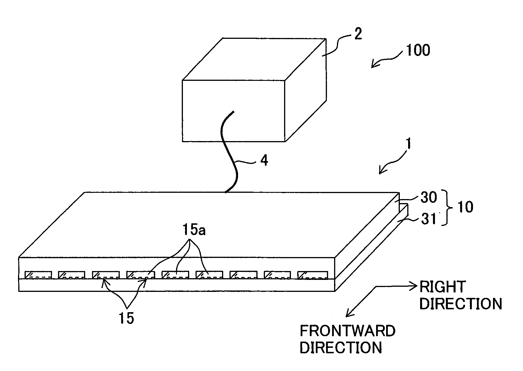
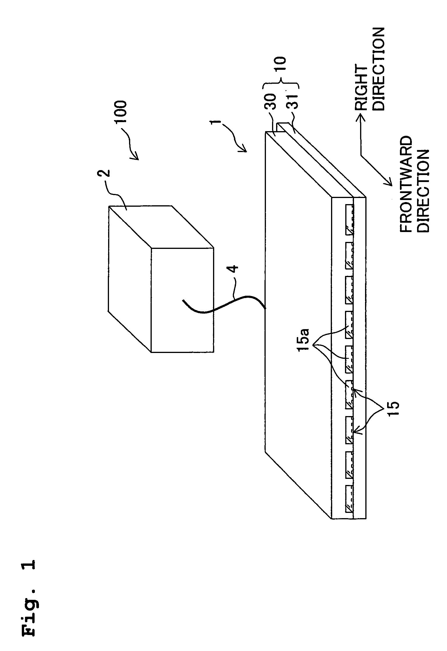
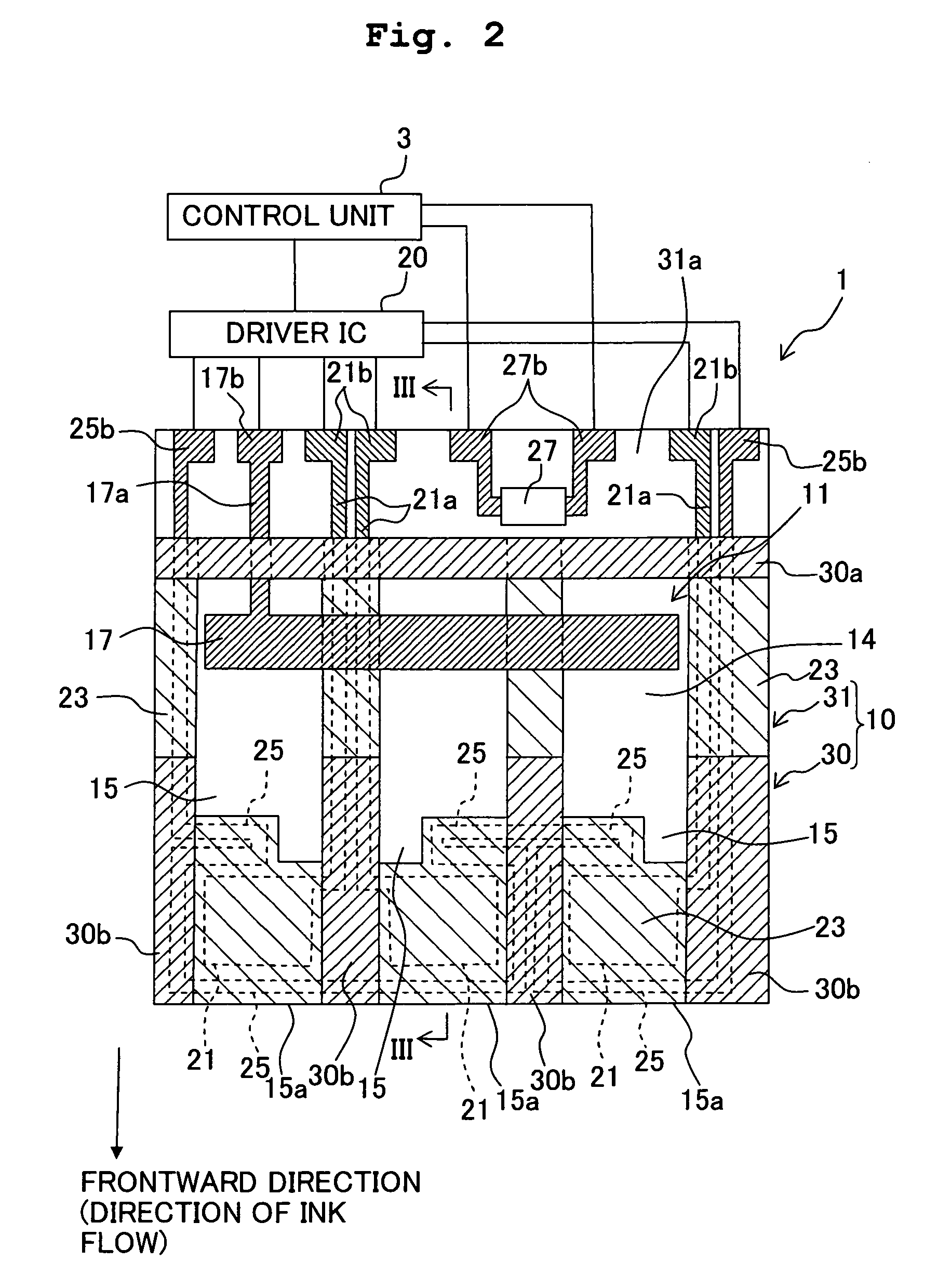
[0052]FIG. 1 is a perspective view showing schematically a printer 100 of the embodiment. As shown in FIG. 1, the printer 100 includes an ink-jet head 1 (liquid transporting apparatus) including a plurality of individual channels 15 each provided with a jetting port 15a, an ink tank 2 which is connected to the ink-jet head 1 via a tube 4, and a control unit 3 (refer to FIG. 2) which controls the ink-jet head 1 to transport the ink to the jetting port 15a. Moreover, the printer 100 jets inks from the plurality of jetting ports 15a provided on a front-end surface of the ink-jet head 1, toward a recording paper P position...


PUM


Abstract

An ink transporting head includes a head main body in which, an ink channel is formed, a transporting electrode which is arranged on an inner surface of the ink channel, an insulating layer which is arranged on the inner surface of the ink channel to cover the transporting electrode, and which changes a wetting angle of liquid on a surface according to an electric potential of the transporting electrode, and a heat generator which heats the ink inside the ink channel. Accordingly, there is provided a liquid transporting apparatus which is capable of suppressing a temperature fluctuation of the liquid inside the liquid channel, and transporting the liquid stably.

Description

CROSS-REFERENCE TO RELATED APPLICATION[0001]The present application claims priority from Japanese Patent Application No. 2007-215600, filed on Aug. 22, 2007, the disclosure of which is incorporated herein by reference in its entirety.BACKGROUND OF THE INVENTION[0002]1. Field of the Invention[0003]The present invention relates to a liquid transporting apparatus which transports an electroconductive liquid.[0004]2. Description of the Related Art[0005]A printer in which an ink-jet recording head is installed has hitherto been known as a printer which records an image and the like on a recording medium such as a recording paper. In the ink-jet recording head, a pressure is applied to the ink inside an ink channel to transport the ink to a nozzle, and further, the ink is jetted from the nozzle toward the recording medium. However, in the ink-jet recording head, a channel structure and a structure of an actuator for generating a transporting pressure and a jetting pressure for the ink is ...

Claims


Application Information

Patent Timeline
Patent Type & Authority Applications(United States)
IPC IPC(8): B41J29/38
CPCB41J2002/14395B41J2/14
Inventor SUGAHARA, HIROTO
Owner BROTHER KOGYO KK
Why Eureka
Try Eureka