Inkjet recording system and recording apparatus

a recording system and recording apparatus technology, applied in piezoelectric/electrostrictive/magnetostrictive devices, piezoelectric/electrostriction/magnetostriction machines, printing, etc., can solve the problems of inability to discharge easily, bubbles may occur in the ink flow channel during the ink flow, and the ink chargeability is improved. , the effect of high reliability

Inactive Publication Date: 2009-02-26
KYOCERA DOCUMENT SOLUTIONS INC
View PDF0 Cites 23 Cited by
  • Summary
  • Abstract
  • Description
  • Claims
  • Application Information

AI Technical Summary

Benefits of technology

[0009]It is an object of the present invention to provide an inkjet recording system

Problems solved by technology

However, in an inkjet head, when wettability of ink flow channel provided in the head is poor, bubbles may occur in the ink flow channel during charging of ink.
Furthermore, these bubbles can solidly adhere to the wall face of the flow channel, and will not be discharged easily even if discharging operation by suction of ink is conducted.
When bubbles remain in the ink flow channel, troubles such as dot missing and printing disorder, as well as jet impossibility occur, to deteriorate the printing quality.
However, in the structure disclosed in the patent document in which ink directly con

Method used


Image

  • Inkjet recording system and recording apparatus
  • Inkjet recording system and recording apparatus
  • Inkjet recording system and recording apparatus

Examples


first embodiment

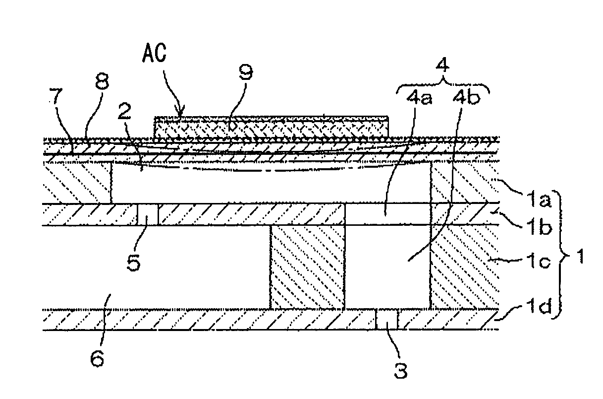
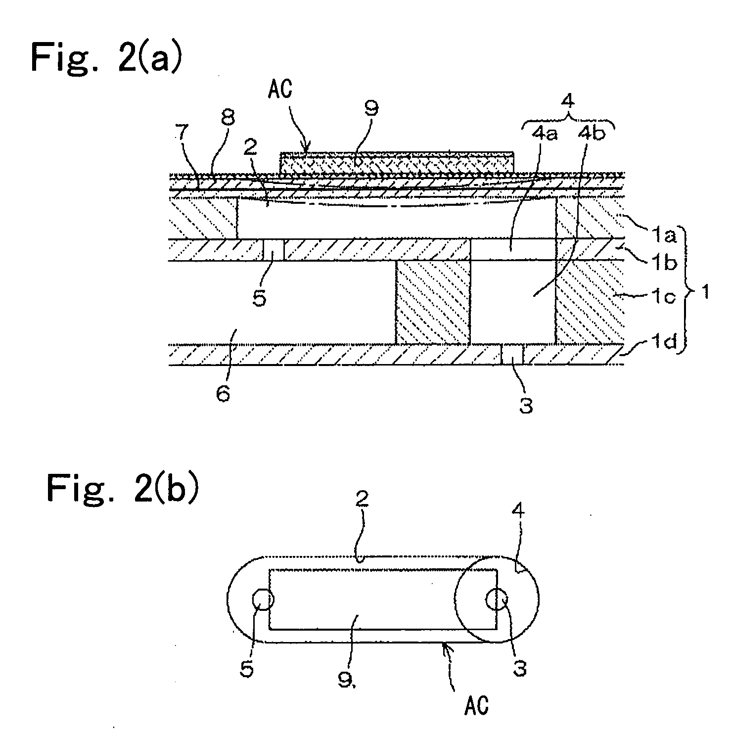
[0026]In an inkjet recording head in the present embodiment, a part of wall face of a pressure chamber in which a nozzle is provided is formed of a piezoelectric element, and the piezoelectric element is activated and deformed to make pressure wave act on ink in the pressure chamber, thereby discharging an ink droplet from the nozzle. Surface of the piezoelectric element forming a part of wall face of the pressure chamber has a centerline average roughness Ra ranging from 0.05 to 2 μm, and contact angle θ with ink is 45 degrees or less, and the above expression (1) is satisfied. Preferably, the contact angle is from 5 to 45 degrees.

[0027]According to the present invention, it was found that ink chargeability for an inkjet recording head has relationship with centerline average roughness of surface of piezoelectric element that directly contacts the ink and causes generation of pressure wave. That is, when centerline average roughness Ra of piezoelectric element is smaller than 0.05 ...

second embodiment

[0066]In the inkjet recording head used in the present embodiment, a part of wall face of the pressure chamber in which a nozzle is provided is formed of a piezoelectric element, and the piezoelectric element is activated and deformed to make pressure wave act on the ink in the pressure chamber, thereby discharging an ink droplet from the nozzle. Average inclination Δa of the piezoelectric element is 100 to 1000 mrad, and contact angle with ink is 45 degrees or smaller, and further, the above expression (2) is satisfied. Preferably, the contact angle is from 5 to 45 degrees.

[0067]According to the present invention, it was revealed that ink chargeability for the inkjet recording head has a relation to average inclination of surface of the piezoelectric element that directly contacts the ink to cause generation of pressure wave. That is, when average inclination Δa of the piezoelectric element exceeds 1000 mrad, the time required for the ink to achieve a desired charging ratio is exte...


PUM


Abstract

An inkjet recording system including an inkjet recording head in which a part of wall face of a pressure chamber in which a nozzle is provided is formed of a piezoelectric element, the piezoelectric element being activated and deformed to make pressure wave act on ink in the pressure chamber, thereby discharging an ink droplet from the nozzle, wherein surface of the piezoelectric element forming a part of wall face of the pressure chamber has a centerline average roughness Ra ranging from 0.05 to 2 μm, and contact angle θ with ink is 45 degrees or less, and the following expression (1) is satisfied;
A cos2θ>0.04  (1)
wherein A represents centerline average roughness Ra (μm) of surface of piezoelectric element forming wall surface of pressure chamber, and θ represents contact angle of ink with respect to piezoelectric element.

Description

BACKGROUND OF THE INVENTION[0001]1. Field of the Invention[0002]The present invention relates to inkjet recording systems and recording apparatuses having excellent ink chargeability.[0003]2. Description of Related Art[0004]Recent outstanding improvement in inkjet recording technique has enabled production of high-definition images which are very similar to photographs. Consequently, inkjet recording has been widely used in various fields of art. In association with this, there is a need of improving printing speed as well as obtaining high-definition images. As a measure for improving printing speed, there is known a method of increasing the number of nozzles, and discharging ink droplet in larger amount per unit time from each head. In such a measure, driving frequency of 15 kHz or higher is desired, and it is necessary to supply ink that is to be used in unit time by every head without any excess and deficiency from an ink cartridge.[0005]However, in an inkjet head, when wettabil...

Claims


Application Information

Patent Timeline
IPC IPC(8): B41J2/045
CPCB41J2/14209B41J2202/11B41J2202/03
Inventor HIROSHIMA, SUSUMU
Owner KYOCERA DOCUMENT SOLUTIONS INC
Why Eureka
Try Eureka