Defect repairing method of liquid crystal display and signal transmission method of source driver and timing controller thereof

Inactive Publication Date: 2009-02-26
HIMAX TECH LTD
View PDF11 Cites 14 Cited by
  • Summary
  • Abstract
  • Description
  • Claims
  • Application Information

AI Technical Summary

Benefits of technology

[0008]The invention is directed to a liquid crystal display (LCD) and a data transmission method thereof. The LCD advantageously has the fewer redundant lines, the shorter data transmission path formed after repair, the fewer times of laser welding required for the repair, and the lower cost.

Problems solved by technology

Consequently, the data channel tends to have the problem of the insufficient data driving ability.
Therefore, the problem of the data driving ability becomes more obvious.
Thus, the cost of the LCD is increased.

Method used


Image

  • Defect repairing method of liquid crystal display and signal transmission method of source driver and timing controller thereof
  • Defect repairing method of liquid crystal display and signal transmission method of source driver and timing controller thereof
  • Defect repairing method of liquid crystal display and signal transmission method of source driver and timing controller thereof

Examples


first embodiment

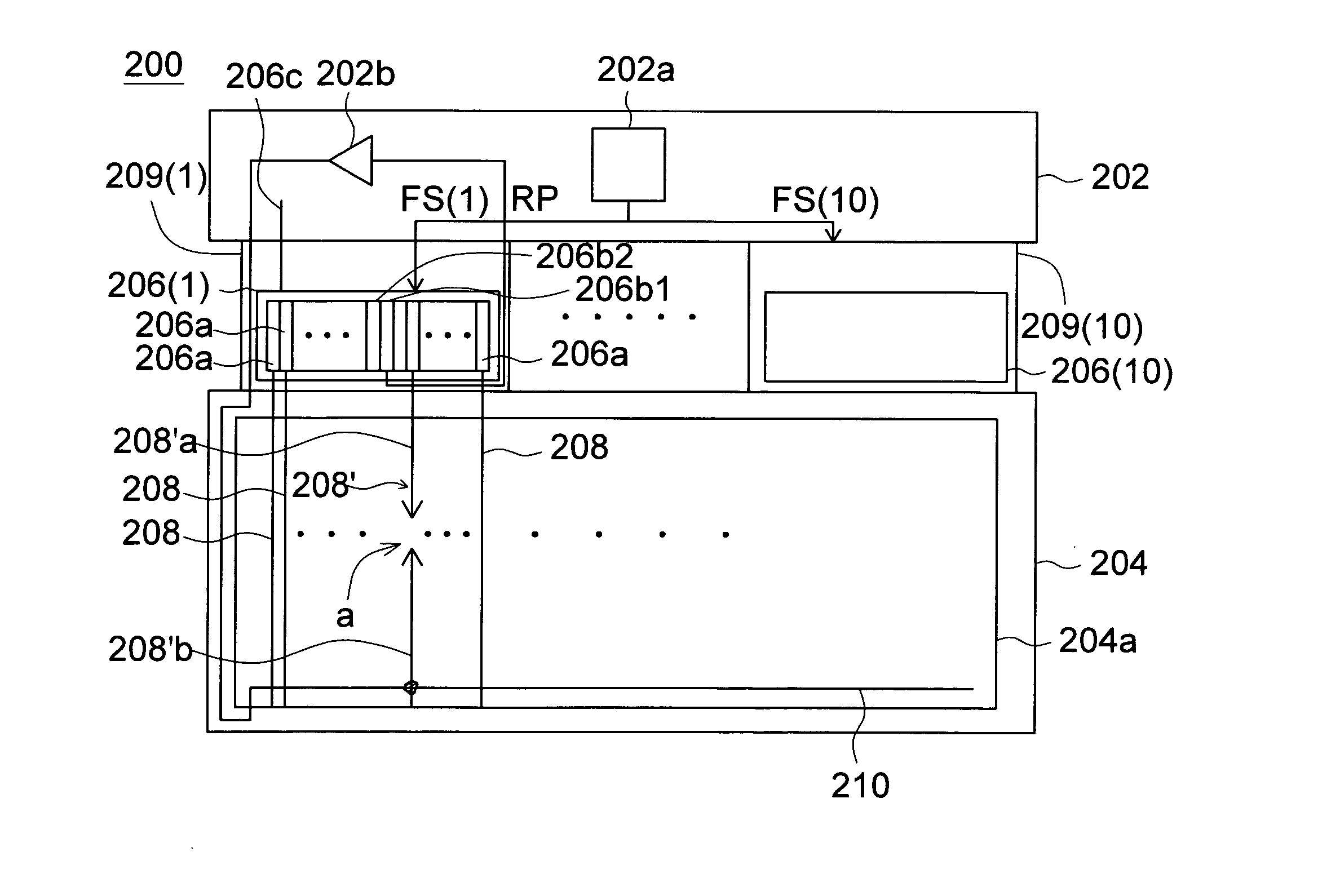
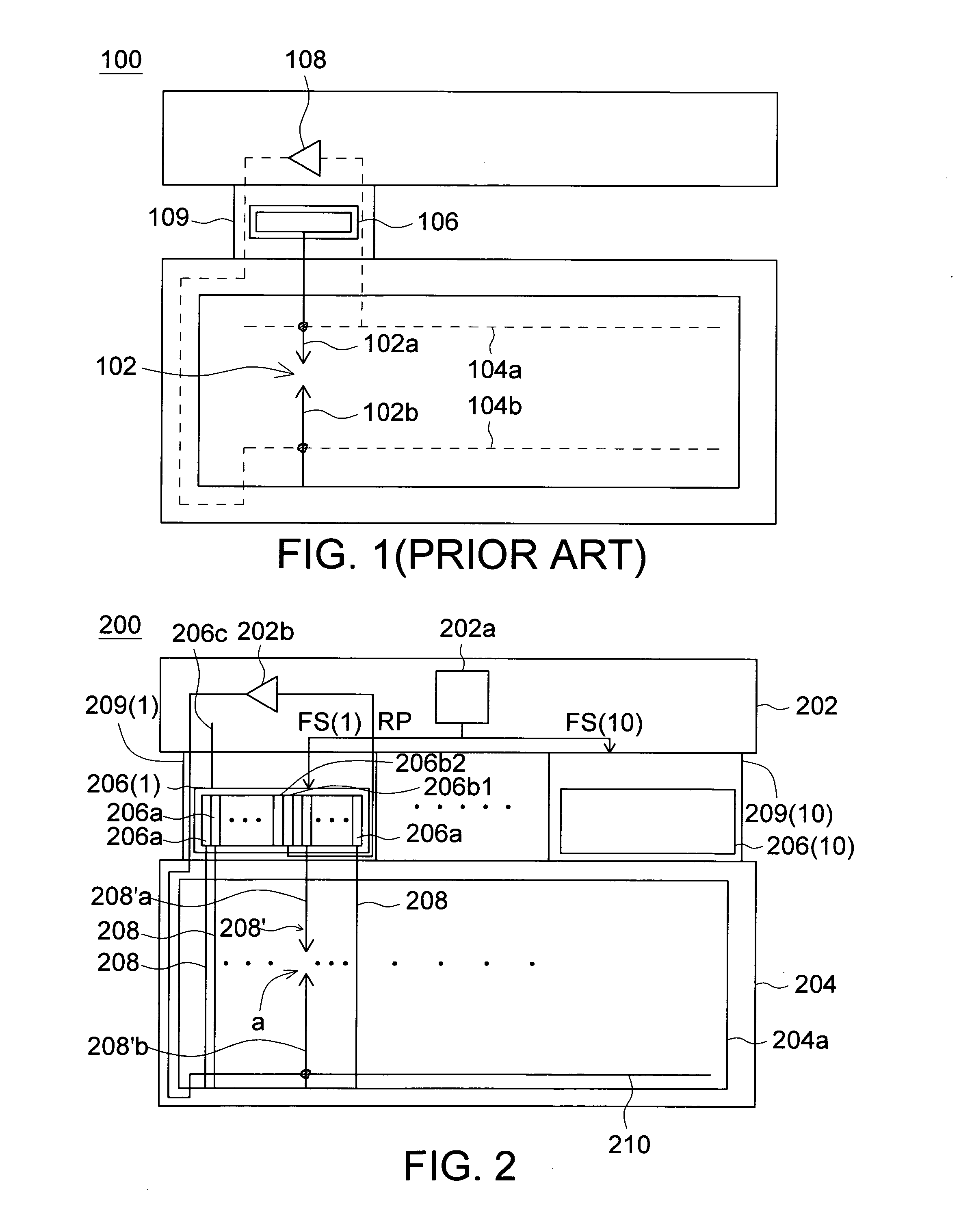
[0025]FIG. 2 is a circuit diagram showing a LCD 200 according to a first embodiment of the invention. Referring to FIG. 2, the LCD 200 includes a printed circuit board (PCB) 202, a substrate 204, source drivers 206(1) to 206(10) and flexible printed circuits (FPCs) 209(1) to 209(10). The substrate 204 includes a LCD panel 204a, which includes multiple data lines 208, redundant lines 210 and a pixel array (not shown). The LCD panel 204a has the resolution of 1280×1024 pixels, for example. Each pixel includes red, green and blue (RGB) sub-pixels, for example. The PCB 202 includes a controller and a repair operational amplifier 202b, wherein the controller is a timing controller (TCON) 202a. The FPCs 209(1) to 209(10) respectively have the source drivers 206(1) to 206(10).

[0026]The timing controller 202a outputs image data FS(1) to FS(10) to the source drivers 206(1) to 206(10). The source drivers 206(1) to 206(10) are also referred to as source driver circuits and respectively receive...

second embodiment

[0048]FIG. 7 is a circuit diagram showing a LCD 400 according to a second embodiment of the invention. As shown in FIG. 7, what is different from FIG. 2 is that a repair operational amplifier 406d of the LCD 400 is designed in a source driver 406(1).

[0049]FIG. 8 is a circuit layout diagram showing the source driver 406(1) of FIG. 7. As shown in FIG. 8, the source driver 406(1) includes 386 channel circuits including 384 data channel circuits 502 and two repair channel circuits 504. The repair channel circuits 504 are located at a middle of the 384 data channel circuits 502, for example. The source driver 406(1) includes two repair operational amplifiers 506 and 508. In this embodiment, only the circuit layout diagram of the source driver 406(1) is illustrated. However, the structures of source drivers 406(2) to 406(10) may be analogized according to the structure of the source driver 406(1).

[0050]FIG. 9 is another circuit layout diagram showing the source driver 406(1) of FIG. 7. As...


PUM


Abstract

A liquid crystal display (LCD) includes a controller, a source driver, first and second data lines and a data transmission path. The controller outputs first and second image data, and the source driver receives and outputs the first and second image data. The source driver includes first and second data channel circuits and a first repair channel circuit. The first and second data channel circuits respectively output first and second sub-pixel data. The first repair channel circuit is coupled to the controller to receive first repairing data. The first and second data lines are respectively coupled to the first and second data channel circuits to receive the first and second sub-pixel data. The data transmission path includes a redundant line, which is for coupling the first repair channel circuit to one of the first and second data lines, and interlaces with the first and second data lines.

Description

[0001]This application claims the benefit of Taiwan application Serial No. 0 96130967, filed Aug. 21, 2007, the subject matter of which is incorporated herein by reference.BACKGROUND OF THE INVENTION[0002]1. Field of the Invention[0003]The invention relates in general to a liquid crystal display (LCD), and more particularly to a LCD having a repair channel through which an open defect of the LCD can be repaired.[0004]2. Description of the Related Art[0005]In a liquid crystal panel of a conventional LCD, multiple redundant lines have to be provided so that data repairing can be performed through the redundant line and the opened data line by way of laser welding when the data line of the LCD has an open defect.[0006]FIG. 1 (Prior Art) is a schematic illustration showing an operation of repairing an open defect of a data line in a conventional LCD 100. In the LCD 100, when a data line 102 has an open defect, the data line 102 forms a normal end 102a and a to-be-repaired end 102b. At t...

Claims


Application Information

Patent Timeline
IPC IPC(8): G02F1/1333
CPCG09G3/006G09G2330/08G09G3/3611G09G3/36
Inventor CHEN, CHIEN-CHUNCHEN, YING-LIEHBU, LIN-KAI
Owner HIMAX TECH LTD
Why Eureka
Try Eureka