
Scaffold connection with concave engagement and gravity lock

a technology of concave engagement and gravity lock, which is applied in the direction of couplings, building scaffolds, mechanical devices, etc., can solve the problems of difficult installation and removal of the wedge connection, and achieve the effect of good engagement and high resistance to accidental disconn

Inactive Publication Date: 2009-02-26
WILLIAMS JOE W
View PDF27 Cites 30 Cited by
  • Summary
  • Abstract
  • Description
  • Claims
  • Application Information

AI Technical Summary

Benefits of technology

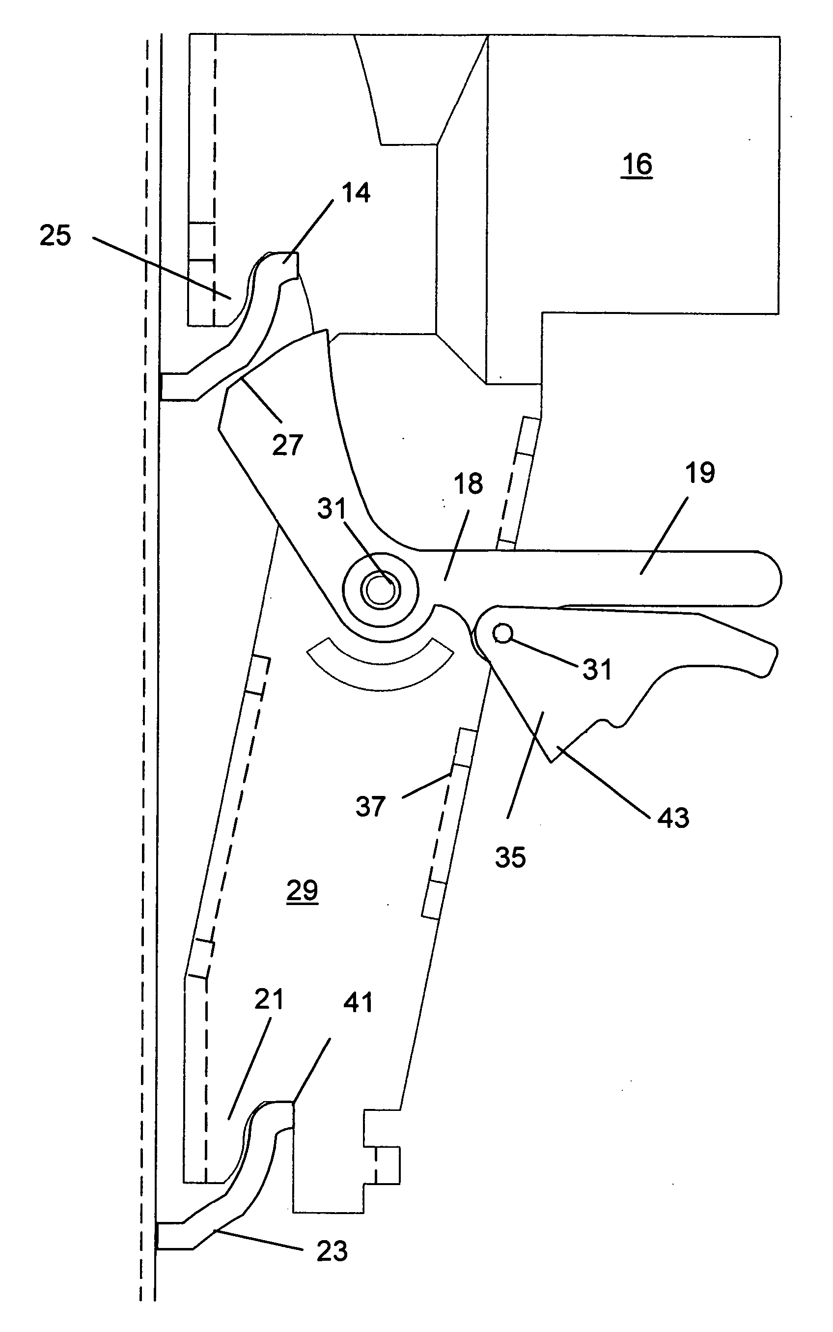
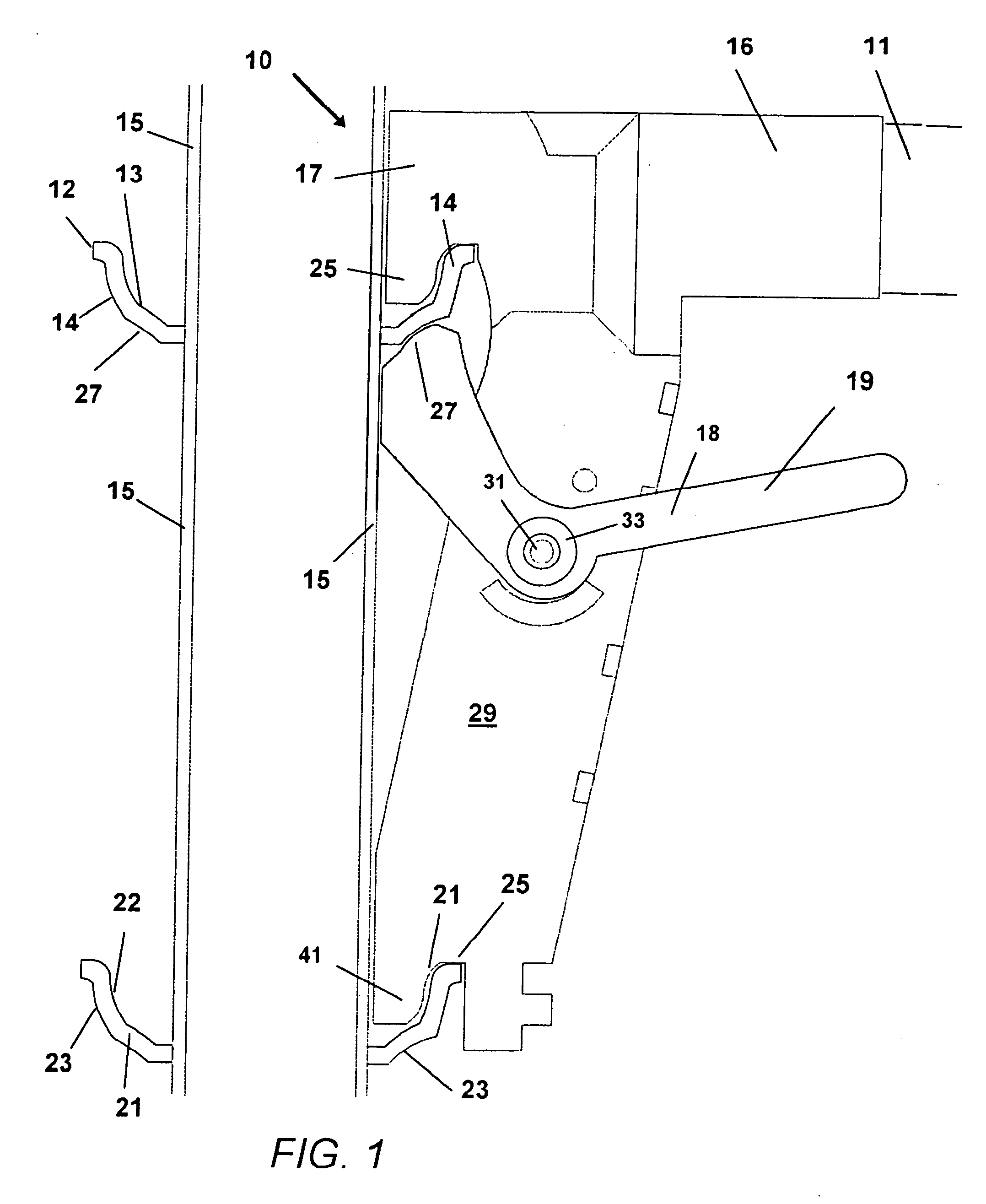
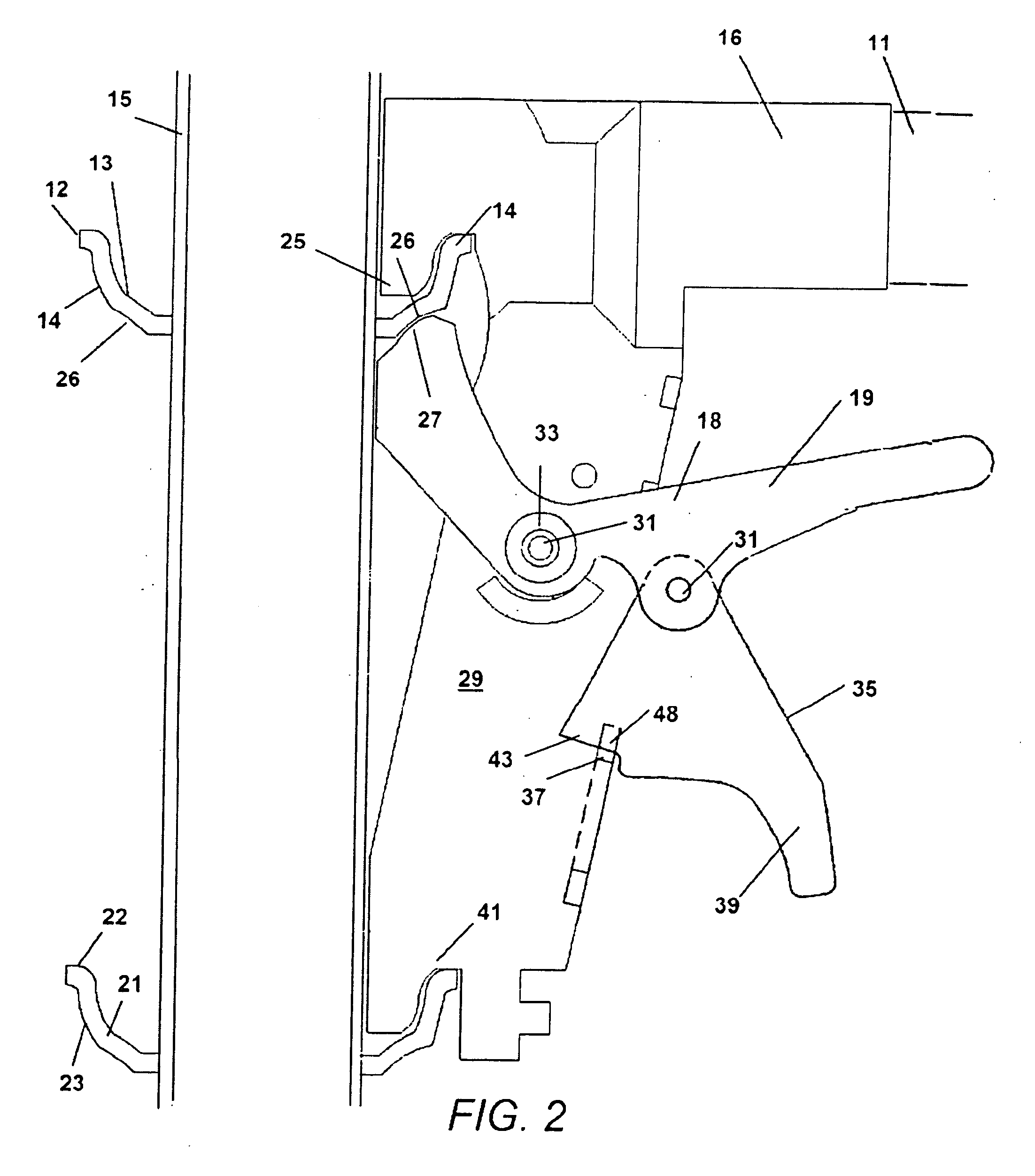
[0011]In a marked improvement to this system the lower side of the first ring member is concave in shape and the support surface of the latch member has a complimentary shape so as to settle into the concave lower side when positioned below it. This engagement of the concave lower surface of the ring member and curved support surface of the latch, provides an especially good engagement that has shown to be highly resistant to any accidental disconnect when the horizontal member or the connector body is struck with force from the side, such as by a worker walking on the scaffold falling against it and producing lateral force to the connection.

Problems solved by technology

However, the wedge form of connection is hard to install and remove as it requires the wedge to be driven in and out with tools.
While these devices have been more successful in shortening installation times since tools are not required, recently a concern has arisen due to the dislodgement of horizontal members occurring if the triggered ring connection is struck with a lateral force such as a worker hitting a horizontal member with their body too hard.

Method used


Image

  • Scaffold connection with concave engagement and gravity lock
  • Scaffold connection with concave engagement and gravity lock
  • Scaffold connection with concave engagement and gravity lock

Examples


Embodiment Construction

[0016]Referring now to the drawings, FIGS. 1-3 depict various modes of the disclosed device 10 for engagement of scaffold members in construction of scaffolds and similar structures. The Figures depict various embodiments of the improved scaffold connection device 10, all of which incorporate the unique concave engagement of components which yield the increased resistance to disengagement of the components.

[0017]As shown in FIGS. 1-3 all modes of the connection device 10 include a first ring member 12, which is fixedly attached to a vertical scaffold member 15, preferably by welding. The first ring member 12 has an upper side 13 surface and a lower side 14 surface surrounding the member 15 in the curved shape of the ring member 12.

[0018]In the most preferred mode of the device 10 shown in FIGS. 2-3, while not required for the engagement of the scaffold components, additional redundancy and stability of the assembled device 10 to the member 15 can be obtained by the addition of secon...


PUM


Abstract

An improved scaffold connection for engagement of scaffold members to support members. The connection employs a ring member engaged to the vertical scaffold member. A rotatable latch member engages a lower surface of the ring member to maintain a hook or support portion of a latch body on the upper surface of the ring member. A locking member rotationally engaged to the latch member, is gravity activated to rotate and engage the latch body to hold the latch member engaged to the ring member.

Description

[0001]This application claims the benefit of U.S. Provisional Application No. 60 / 932861 filed Jun. 1, 2007 and incorporated herein in its entirety by reference. This invention relates generally to connections for scaffolding. More particularly the disclosed device relates to an improved scaffolding connection employed between horizontal and vertical scaffold members, which is highly resistant to disconnection from impacts and from lateral forces that can impact the horizontal scaffold members.BACKGROUND OF THE INVENTION[0002]1. Field of the Invention[0003]2. Prior Art[0004]Scaffold connection designs for engaging the horizontal members of scaffolding to the vertical members providing support have been employed for hundreds of years in different forms. Modernly, the concern for worker safety has been a driving force for the creation of locking connectors for the horizontal members to the vertical members. Different designs have been taught from annular embers on the vertical posts en...

Claims


Application Information

Patent Timeline
IPC IPC(8): E04G7/00
CPCE04G7/307Y10T403/30Y10T403/24
Inventor WILLIAMS, JOE W.
Owner WILLIAMS JOE W
Learn More