
Method and Device for Collecting Wave Energy

a wave energy and wave energy technology, applied in the field of methods, can solve the problems that the energy contained by the waves cannot be collected in a satisfactory manner, and achieve the effects of reducing loading, reducing risk, and reducing the risk of collision

Inactive Publication Date: 2009-03-05
FINN ESCONE OY +1
View PDF11 Cites 23 Cited by
  • Summary
  • Abstract
  • Description
  • Claims
  • Application Information

AI Technical Summary

Benefits of technology

[0009]An advantage of the invention is that the movements of the float are controlled, since a bar that is rigid relative to the float prevents the float from ending up in unfavourable positions from the point of view of energy collection. A bar rigidly fastened to the float keeps the float on a controlled, circular or elliptical path.
[0010]The essential idea of an embodiment of the invention is that the device comprises means for adjusting the height of the float relative to the surface of water. The mass of the float can be varied for instance by varying the amount of water or air inside the float. In this way, the float can be adjusted in such a manner that it receives the energy contained by the waves in the best possible manner under prevailing wave conditions. Furthermore, it is possible to adjust the float deep in the water in view of storms and ice conditions, whereby damage to the collecting device is avoided. On the other hand, under wave conditions corresponding to normal operating circumstances, the float can be kept at the upper surface layer of water, immediately below the surface by means of adjustment; a location wherein the energy contained by the waves is at its maximum.
[0023]The essential idea of an embodiment of the invention is that the horizontal movement of the float is restricted in a direction transverse to the direction of motion of the waves. This enables the placement of a plurality of collecting devices laterally adjacently without any risk of collision. Furthermore, motion delimiters can be used to lessen the loadings directed to the support bars, the articulations and the rest of the construction.
[0024]The essential idea of an embodiment of the invention is that at least one support bar has a flat cross-section, and that the support bar is arranged to have a relatively large surface area in a direction transverse to the direction of motion of the wave, but at the same time a relatively small surface area against the direction of motion of the wave. This being so, the support bar may prevent lateral movements of the float, however, without its flow resistance in the water being high.

Problems solved by technology

However, the problem in such a collecting device is that the movements of the float are not controlled, and thereby the energy contained by the waves cannot be collected in a satisfactory manner.

Method used


Image

  • Method and Device for Collecting Wave Energy
  • Method and Device for Collecting Wave Energy
  • Method and Device for Collecting Wave Energy

Examples


Embodiment Construction

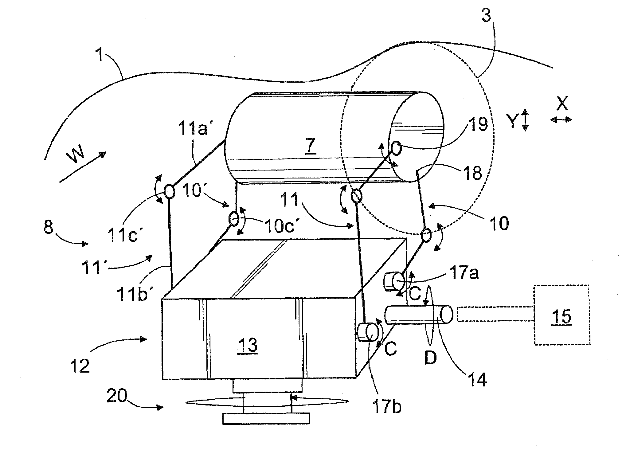
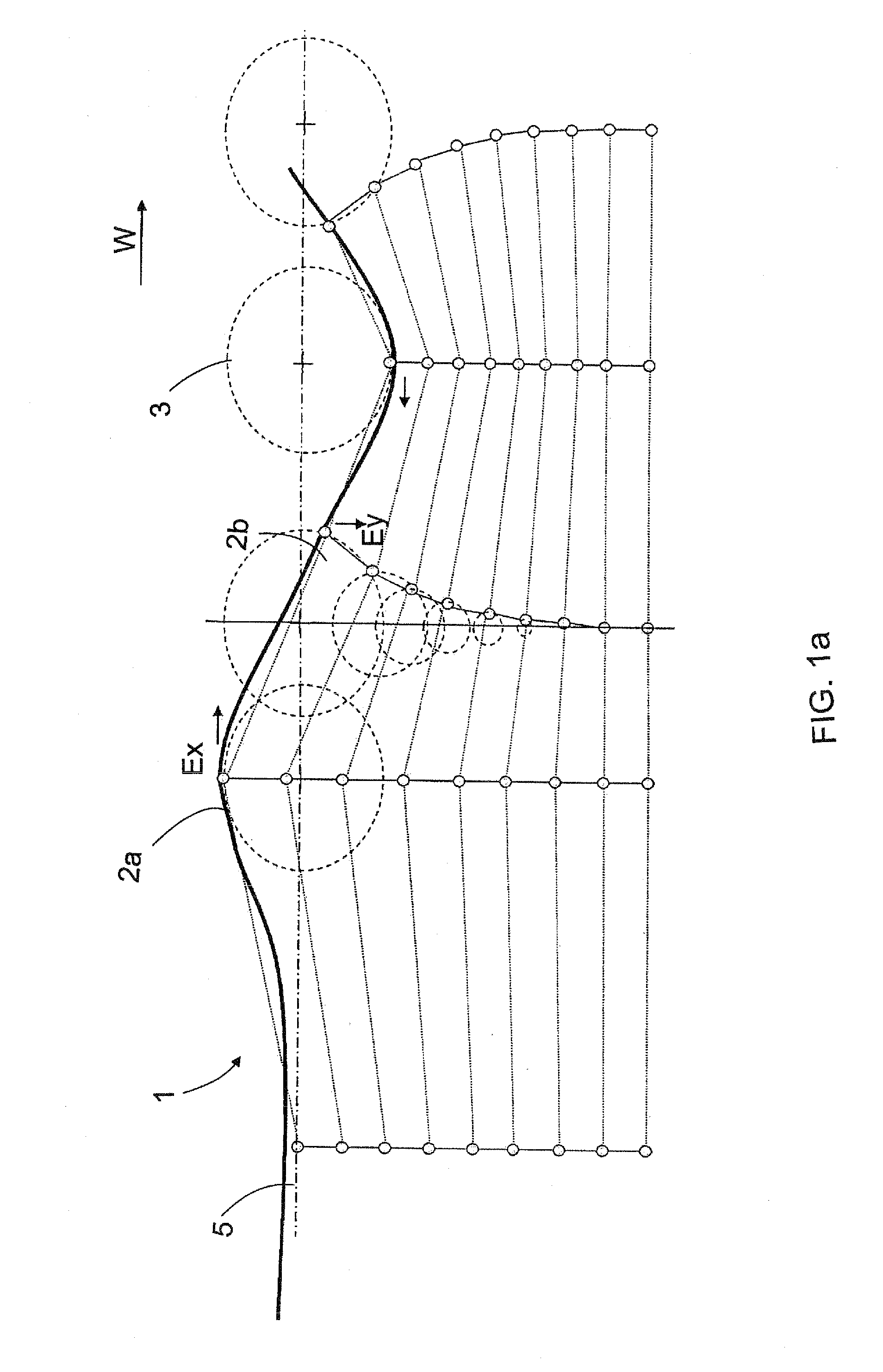
[0048]Waves 1 shown in FIGS. 1a and 1b comprise both potential energy Ey and motion energy Ex. Potential energy Ey is generated as a result of a variation in the height of the water molecules in the vertical direction Y. Motion energy Ex, in turn, is generated as a result of a reciprocating horizontal motion of the water molecules 2. When the water molecule 2 is close to the trough of a wave 1, its potential energy Ey is low and motion energy Ex high. The situation is reverse for a water molecule 2 at the crest of a wave 1. By the action of these two simultaneous energies Ex, Ey, the water molecules 2 move along a circular or elliptical, curved path 3. This motion of the water molecules 2 extends by a distance from the surface 5 of water towards the bottom 6. The depth of the motion of the water molecules depends for instance on the magnitude of the distance from the surface 5 to the bottom 6. Similarly, the shape of the curved path 3 depends for instance on the distance of the surf...


PUM


Abstract

The invention relates to a method and a device for recovering energy contained by waves. The collecting device (8) comprises a float (7) coupled by means of one or more support bars (10, 11) to an actuator (12). At least one support bar is rigidly coupled to the float (7) or to a support member (62) in the float. In addition, the float (7) is arranged substantially entirely below water level.

Description

BACKGROUND OF THE INVENTION[0001]The invention relates to a method of recovering energy contained by waves, and to a collecting device. The object of the invention is more specifically disclosed in the preambles of the independent claims of the application.[0002]Several solutions have been presented for collecting wave energy and for converting it into pressure energy. FR publication 2 436 888 discloses a float on the surface of water, supported to the body of a collecting device by means of bars articulated to the float. Hydraulic pumps are arranged in connection with the bars for generating hydraulic power as the float moves by the action of waves. However, the problem in such a collecting device is that the movements of the float are not controlled, and thereby the energy contained by the waves cannot be collected in a satisfactory manner.BRIEF DESCRIPTION OF THE INVENTION[0003]The object of the present invention is to provide a new and improved method and device for recovering e...

Claims


Application Information

Patent Timeline
IPC IPC(8): F03B13/16F03BF03B13/18
CPCF03B13/181F03B13/1815F03B13/182F03B13/186Y02E10/38F05B2240/40F05B2240/90F05B2260/4031F05B2260/50F03B13/1885Y02E10/30
Inventor RAIKAMO, ESKOOIKARAINEN, MARKKU
Owner FINN ESCONE OY
Features
  • Generate Ideas
  • Intellectual Property
  • Life Sciences
  • Materials
  • Tech Scout
  • Unparalleled Data Quality
  • Higher Quality Content
  • 60% Fewer Hallucinations
Learn More