Labyrinth compression seal and turbine incorporating the same

a technology of compression seals and cylinders, which is applied in the direction of machines/engines, mechanical equipment, liquid fuel engines, etc., can solve the problems of increasing the complexity of gas turbines and the inability to use brush seals, so as to improve the axial sealing of secondary air flow and reduce the pressure gradient

Inactive Publication Date: 2009-03-05
GENERAL ELECTRIC CO
View PDF7 Cites 21 Cited by
  • Summary
  • Abstract
  • Description
  • Claims
  • Application Information

AI Technical Summary

Benefits of technology

[0005]The invention provides a unique means to improve axial sealing of secondary air flow in the wheel spaces of gas turbines. As presently proposed, it is used in conjunction with commonly used labyrinth-type seals that provide a seal between a rotating component and a stationary component. More specifically, the invention introduces a uniquely configured rotating seal tooth which produces a compression mechanism to counter leakage flow through the labyrinth of seal teeth, thereby lessening the pressure gradient that drives leakage and reversing the direction of some of the leakage flow.

Problems solved by technology

This presents a challenge since the sealing mechanism must be devised to provide a means to effectively seal between rotating components (buckets / blades / disks / spacers) and stationary components (nozzles / vanes / diaphragms).
However, most large gas turbines experience additional closure during hot start-up transients which results in the seal teeth cutting deeper into the abradable wall during the transient start but then opening to expose an enlarged gap during steady state operation.
Brush seals can further reduce leakages, but they are costly and increase the complexity of the gas turbine.
Also, there is a limited length that the brush seal bristles can be extended beyond the housing that contains them, and if the transient closure is too large, brush seals cannot be used without risk of a hard rub between the brush seal housing and the rotating components.

Method used


Image

  • Labyrinth compression seal and turbine incorporating the same
  • Labyrinth compression seal and turbine incorporating the same
  • Labyrinth compression seal and turbine incorporating the same

Examples


Embodiment Construction

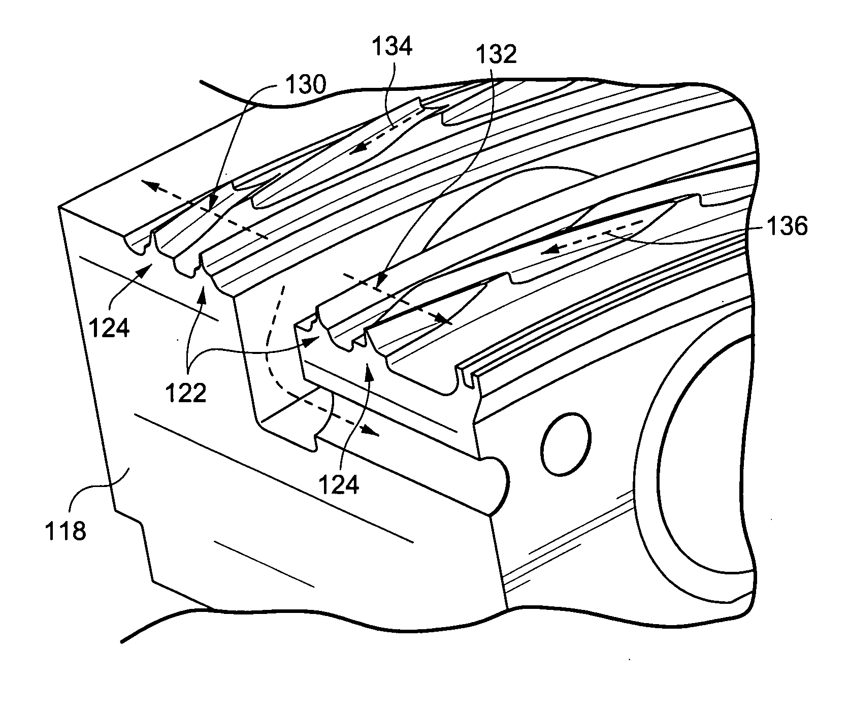
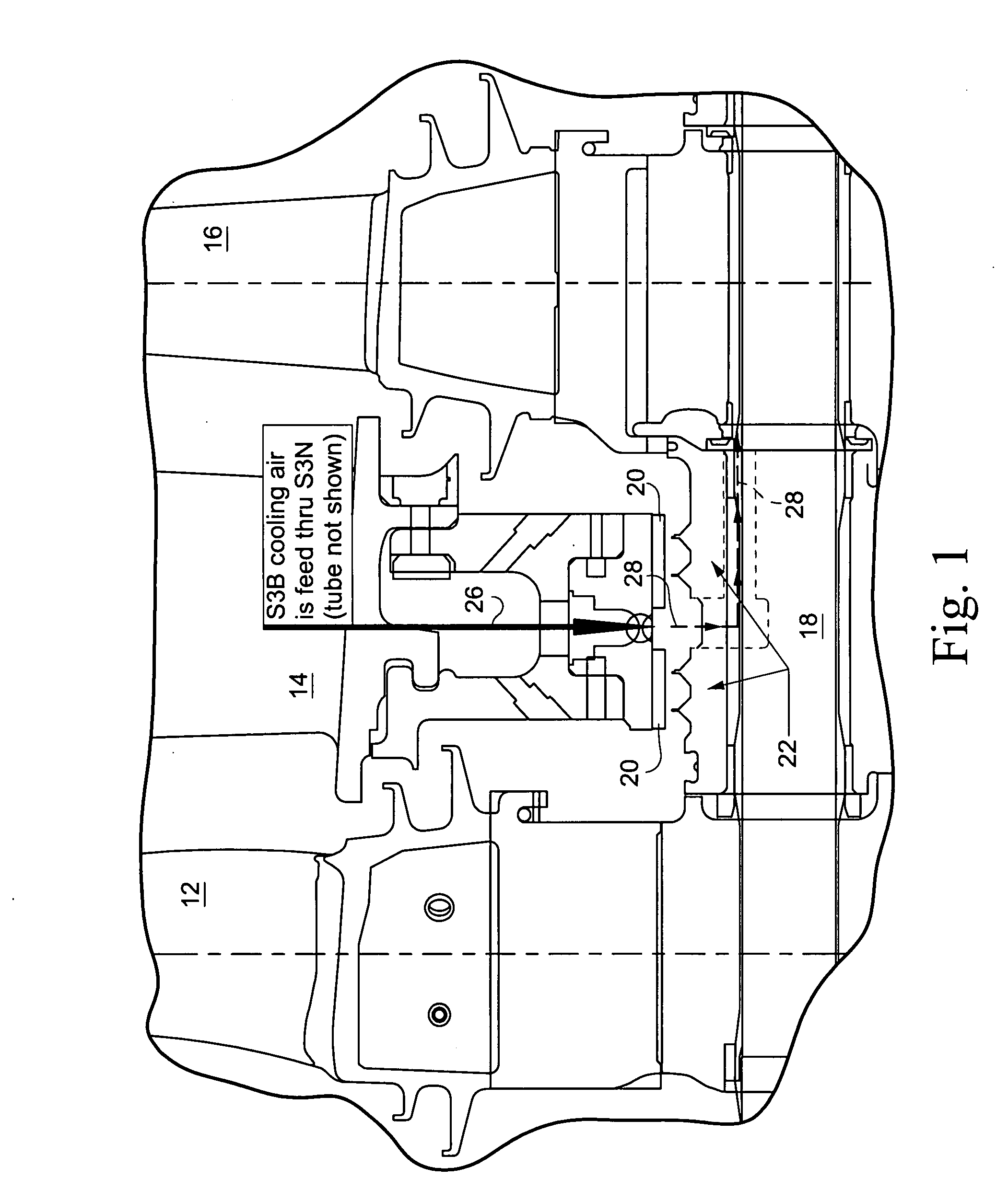
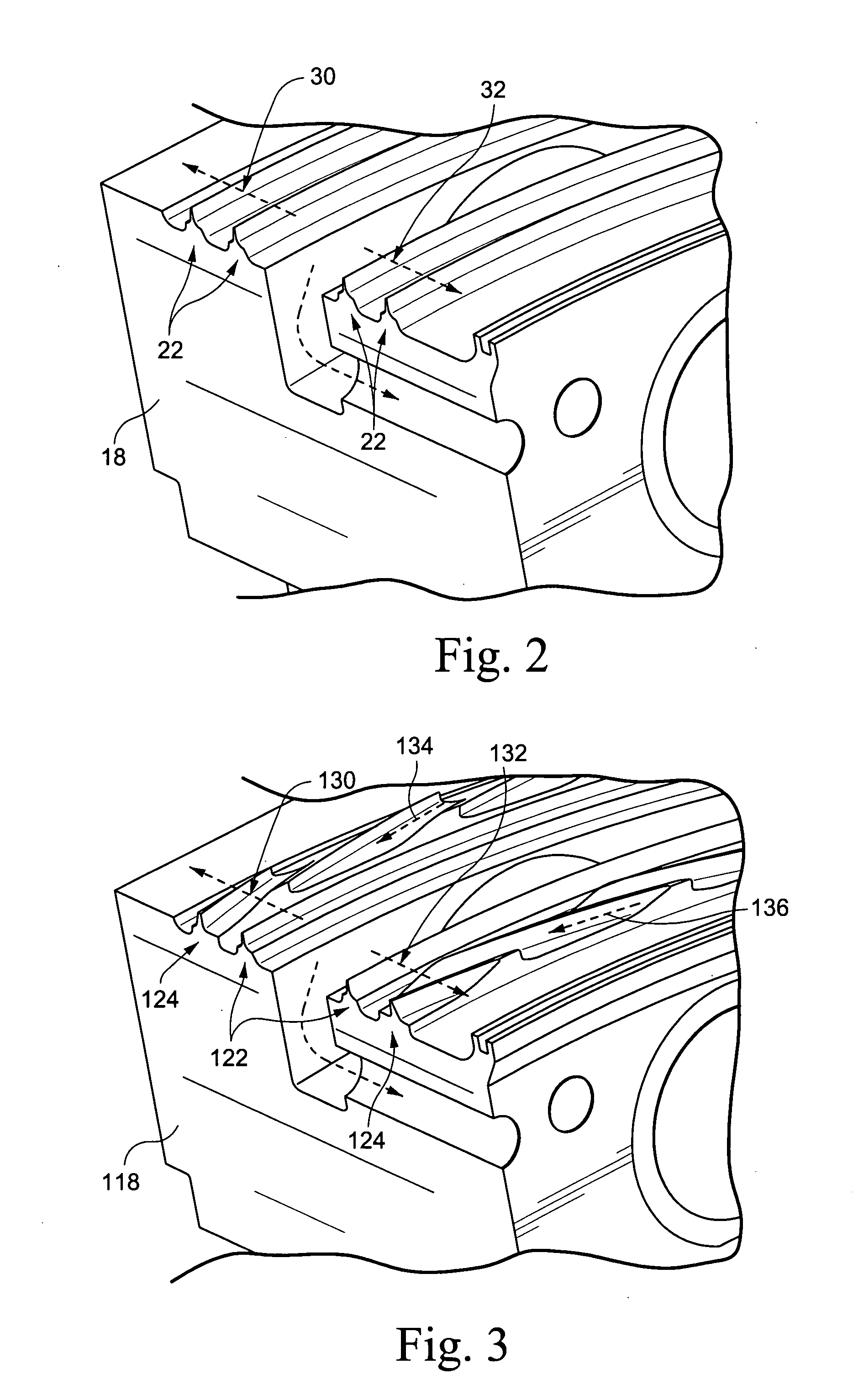
[0014]In an embodiment of the invention, a unique structure is provided to improve axial sealing of secondary air flow in the wheel spaces of gas turbines. As presently proposed, it is used in conjunction with commonly used labyrinth-type seals that provide a seal between a rotating component and a stationary component. More specifically, the invention introduces a uniquely configured rotating seal tooth which produces a compression mechanism to counter leakage flow through the labyrinth of seal teeth, thereby lessening the pressure gradient that drives leakage and reversing the direction of some of the leakage flow.

[0015]In an example embodiment, the present invention avoids the cost, complexities and risks associated with brush seals by reconfiguring the shape and arrangement of labyrinth teeth to create a compression or reverse pumping of the leakage flow. Thus, unlike like brush seals, according to an aspect of the invention does not add additional components. Instead, features ...


PUM


Abstract

A uniquely configured rotating seal tooth is used in conjunction with commonly used labyrinth-type seals that provide a seal between a rotating component and a stationary component. The uniquely configured rotating seal tooth produces a compression mechanism to counter leakage flow through the labyrinth of seal teeth, thereby lessening the pressure gradient that drives leakage and reversing the direction of some of the leakage flow.

Description

BACKGROUND OF THE INVENTION[0001]The present invention relates to a unique seal structure for improving axial sealing of secondary air flow in the wheel spaces of gas turbines.[0002]Obtaining high performance levels in a gas turbine requires minimizing leakages of secondary air throughout the wheel spaces. This presents a challenge since the sealing mechanism must be devised to provide a means to effectively seal between rotating components (buckets / blades / disks / spacers) and stationary components (nozzles / vanes / diaphragms). It is common practice to use labyrinth type seals which restrict the area where the leakage might occur and also create a series of pressure loss mechanisms to further reduce the flow of air leakage. Different arrangements of labyrinth seal teeth have been used, some aligned circumferentially, some staggered circumferentially. Also, different numbers of seal teeth are commonly used in series to provide additional pressure losses and further reduce leakage when ne...

Claims


Application Information

Patent Timeline
Patent Type & Authority Applications(United States)
IPC IPC(8): F16J15/447F01D11/08
CPCF01D11/02F01D11/001
Inventor BULGRIN, CHARLES ALANBRUNER, RALPH CHRISAKIN, ROBERT CRAIG
Owner GENERAL ELECTRIC CO
Why Eureka
Try Eureka