
Hydraulic coupling device and components and method related thereto

a technology of hydraulic coupling and components, applied in the direction of couplings, nuts, pipe elements, etc., can solve the problems of increased separation forces between the coupling units, increased stress on the attachment, and lack of space between the different couplings, so as to optimize service life and uniform torque application

Active Publication Date: 2009-03-05
OILQUICK
View PDF62 Cites 4 Cited by
  • Summary
  • Abstract
  • Description
  • Claims
  • Application Information

AI Technical Summary

Benefits of technology

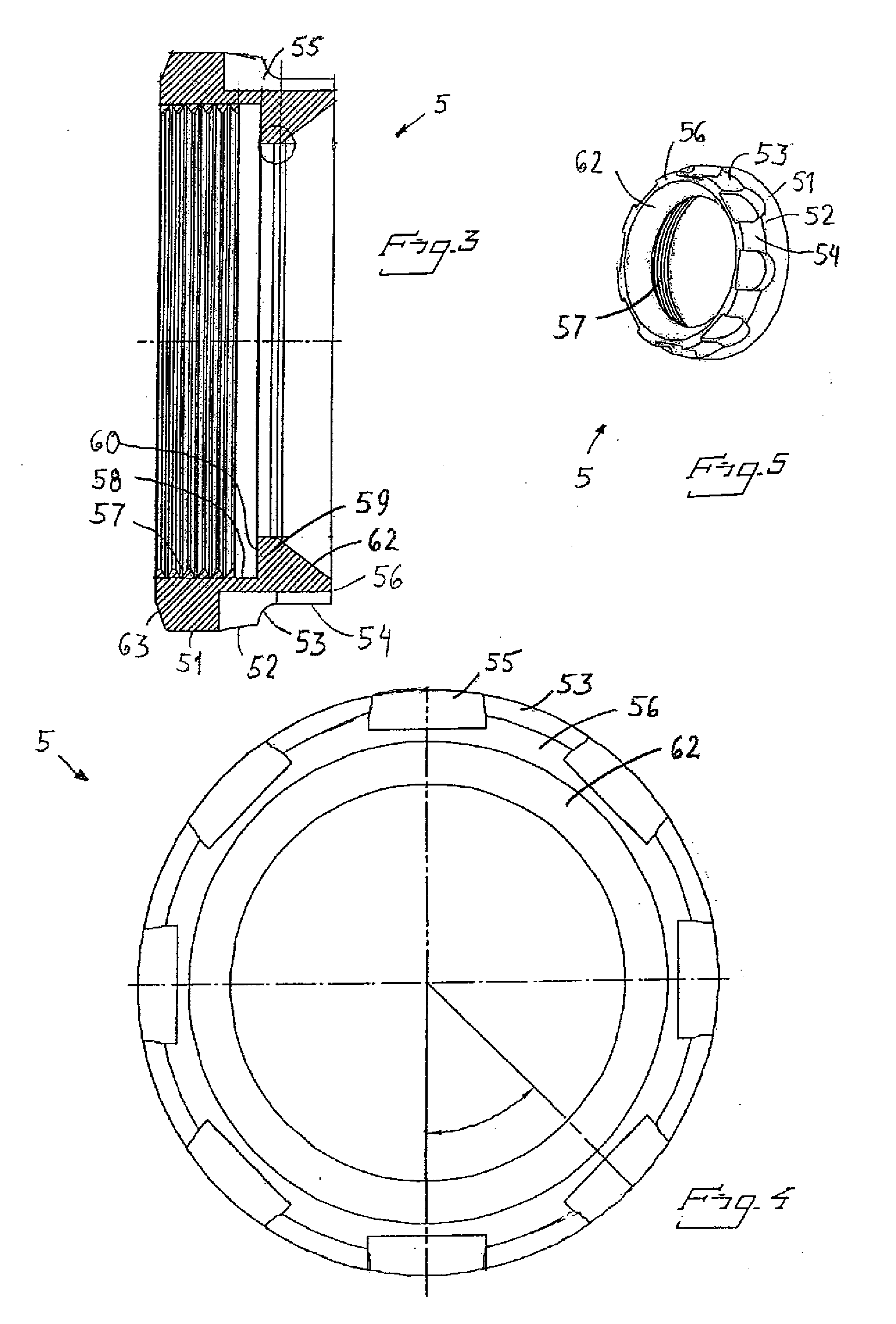
[0016]Thanks to the axial grooves, the lock nut can be turned without any appreciable space in the radial direction being required, where the grooves can be utilized for a uniform application of the torque.
[0037]By means of the invented mounting tool, the hydraulic coupling device according to the invention can be mounted in a simple way.

Problems solved by technology

The development of the hydraulic field moves fast toward higher working pressure, which implies increased separation forces between the coupling units and thereby greater stresses on their attachment.
Another problem that often occurs is that it is narrow and lack of space between the different couplings.
The space and room for mounting tools in connection with mounting and dismounting of couplings and hose connections is another limiting factor.
The problem here is that the joint does not become entirely free of play, which results in wear and possible fracture of the circlip in the case of pulsations and high-pressure surges.
Has clear limitations at large separation forces in the hydraulic system.
The disadvantage is that it is hard to gain access in repair mounting out in the field.
Furthermore, in the case of individual mounting, it is often too little space to get a sufficient dimension of the attachment.
The latter problem is avoided in the case of collective attachment, but here, on the other hand, major problems occur when changing only one coupling.
The disadvantage is that this method requires a relatively large space to have room for a properly dimensioned lock nut and mounting tools in order to mount / dismount the coupling.

Method used


Image

  • Hydraulic coupling device and components and method related thereto
  • Hydraulic coupling device and components and method related thereto
  • Hydraulic coupling device and components and method related thereto

Examples


Embodiment Construction

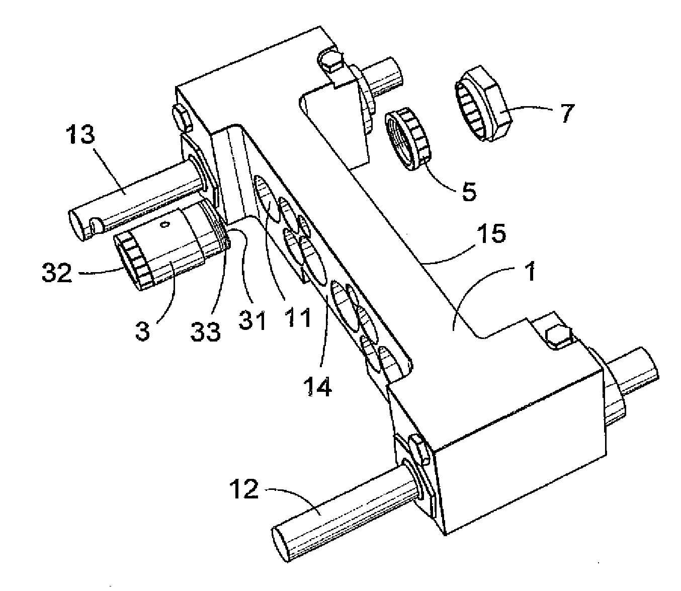
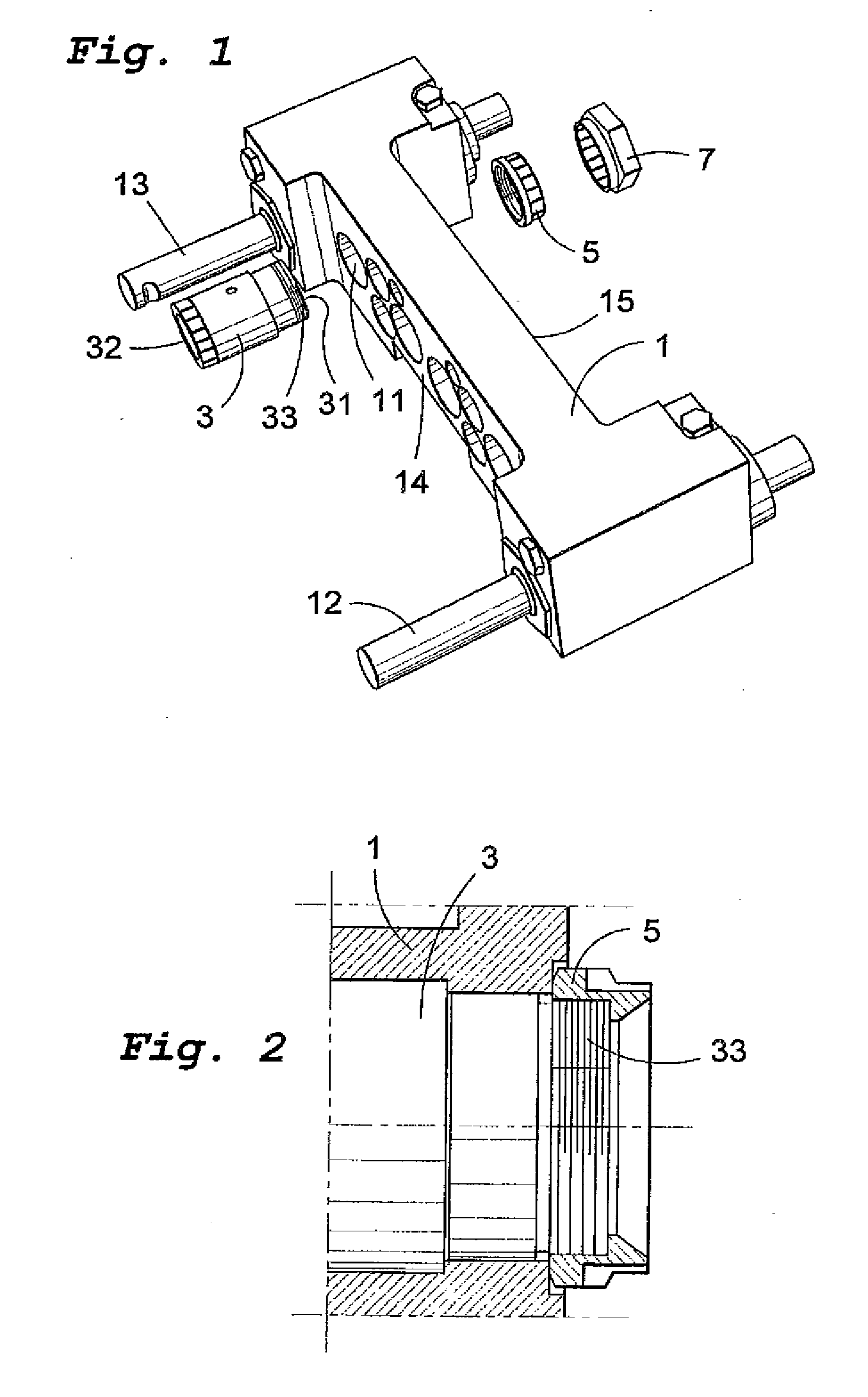
[0050]As FIG. 1 illustrates in a perspective view the included components of the invention, with a holder block 1, a hydraulic coupling unit 3 of the female type, a lock nut 5, and a mounting tool 7.

[0051]The holder block 1 is mounted on a tool attachment of a working machine, the holder block being displaceable on two guide bars 12, 13. When a tool is to be coupled to the tool attachment, a mechanical connection is effected as well as a connection of hydraulic pipes from the working machine to the tool. In doing so, hydraulic coupling units on the holder block 1 are brought to be interconnected with the corresponding coupling units on the tool by the fact that the holder block 1 is displaced by hydraulic control along the guides 12, 13.

[0052]The holder block is provided with a plurality of holes 11 in which the hydraulic coupling units are mounted. The left side of the holder part to the left in the figure is henceforth denominated the back side 14 thereof and the opposite side the...


PUM


Abstract

A hydraulic coupling device, comprising a coupling unit, a holder block, and a lock nut. The coupling unit is mounted to the holder block by means of the lock nut, which is tightened in a thread at the nose end of the coupling unit. The lock nut has a rotationally symmetrical outer contour. A plurality of grooves distributed around the circumference are recessed in the outer contour. The grooves extend axially inward from the end of the lock nut facing away from the holder block. The invention also relates to a lock nut for a hydraulic coupling device, a mounting tool for the lock nut as well as a method for mounting a hydraulic coupling device.

Description

FIELD OF THE INVENTION[0001]In a first aspect, the present invention relates to a hydraulic coupling device comprising a coupling unit, a holder block to which the coupling unit is mounted, and a lock nut for securing the coupling unit to the holder block, which coupling unit has a hose-connection end for the connection to a hydraulic hose, and a nose end for the interconnection with a complementary coupling unit, which nose end is provided with an external thread for the co-operation with the lock nut, so that the lock nut, in the mounted position, secures the coupling unit in the holder block.[0002]In a second aspect, the invention relates to a lock nut for use in the invented hydraulic coupling device.[0003]In a third aspect, the invention relates to a mounting tool for mounting a hydraulic coupling unit to a holder block in the invented hydraulic coupling unit.[0004]In a fourth aspect, the invention relates to a method for mounting a hydraulic coupling unit to a holder block, wh...

Claims


Application Information

Patent Timeline
IPC IPC(8): F16L37/00F16L41/14F16L35/00
CPCF16L41/14F16L37/008
Inventor SONERUD, AKE
Owner OILQUICK
Learn More