Voltage generating apparatus and methods

Inactive Publication Date: 2009-03-05
UPI SEMICON CORP
View PDF4 Cites 0 Cited by
  • Summary
  • Abstract
  • Description
  • Claims
  • Application Information

AI Technical Summary

Benefits of technology

[0009]In one aspect, the invention provides a voltage generating apparatus for powering an amplifier. The voltage generating apparatus comprises a voltage source, a switched capacitor voltage converter and a voltage detector. The voltage source supplies a first voltage to a positive voltage input terminal of the at least one amplifier. The first voltage is a positive DC voltage. The switched capacitor voltage converter is coupled to the voltage source for outputting an output voltage to a negative voltage input te

Problems solved by technology

However, in prior art systems, ripple effects, transients, or other disruptive occurrences may instantaneously produce voltage shot or spike of the specific negative voltage, thereby affecting the lower limit of the operating range.
Consequently, a magnitude of amplification of an input signal from the operational amplifier ac

Method used


Image

  • Voltage generating apparatus and methods
  • Voltage generating apparatus and methods
  • Voltage generating apparatus and methods

Examples


Example

[0018]The following description is of the best-contemplated mode of carrying out the invention. This description is made for the purpose of illustrating the general principles of the invention and should not be taken in a limiting sense. The scope of the invention is best determined by reference to the appended claims.

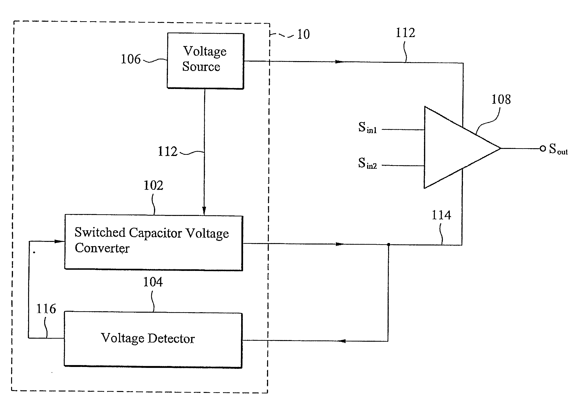
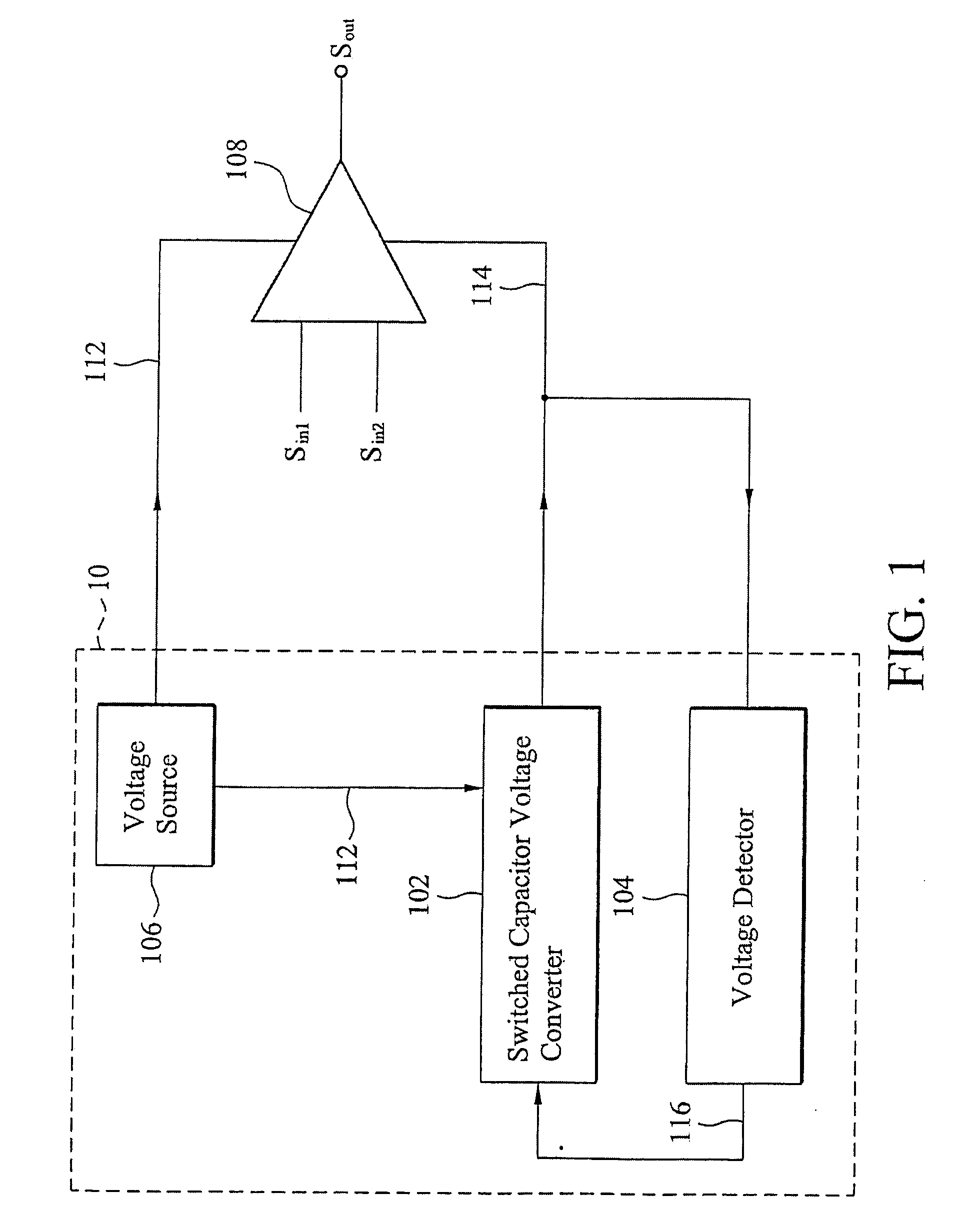
[0019]FIG. 1 is a block diagram of a voltage generating apparatus 10 for driving an amplifier 108 in accordance with one embodiment of the invention. The voltage generating apparatus 10 comprises a voltage source 106, a switched capacitor voltage converter 102 and a voltage detector 104. The voltage source 106 is provided for generating a first voltage 112, where the first voltage 112 is a positive DC voltage outputted to a positive voltage input terminal of the amplifier 108. The switched capacitor voltage converter 102 coupled to the voltage source 106 receives the first voltage 112 and delivers an output voltage 114 to a negative voltage input terminal of the amplif...


PUM


Abstract

The invention provides a voltage generating apparatus for powering at least one amplifier. The voltage generating apparatus comprises a voltage source, a switched capacitor voltage converter and a voltage detector. The voltage source supplies a first voltage to a positive voltage input terminal of the at least one amplifier. The first voltage is a positive DC voltage. The switched capacitor voltage converter is coupled to the voltage source for outputting an output voltage to a negative voltage input terminal of the at least one amplifier according to the first voltage and a predetermined voltage. The output voltage is a negative DC voltage. The voltage detector is coupled to the switched capacitor voltage converter for determining a switching frequency corresponding to the predetermined voltage according to the output voltage. The switched capacitor voltage converter increases the output voltage when the switching frequency is decreased and decreases the output voltage when the switching frequency is increased.

Description

BACKGROUND OF THE INVENTION CROSS REFERENCE TO RELATED APPLICATIONS[0001]This application claims the benefit of U.S. Provisional Application No. 60 / 969,872, filed Sep. 4, 2007, the entirety of which is / are incorporated by reference herein.BACKGROUND OF THE INVENTION[0002]1. Field of the Invention[0003]The invention relates to power supply devices, and more particularly to a voltage generating apparatus and methods for reducing power dissipation and allowing voltage compensation for driving amplifiers.[0004]2. Description of the Related Art[0005]Amplifiers, such as operational amplifiers, are well know in the field of electronic circuits for providing amplification of input signals to drive a variety of electrical loads such as audio speakers. For example, U.S. Pat. No. 7,061,327 illustrates a headphone driver amplifier operative from a single voltage supply, thereby driving headphone speakers. Also, an operational amplifier driven by a charge pump with a single supply voltage is dis...

Claims


Application Information

Patent Timeline
IPC IPC(8): H03F3/04
CPCH03F1/0216
Inventor HSIEH, CHUNG-ANLI, CHENG-TAO
Owner UPI SEMICON CORP
Why Eureka
Try Eureka