Control apparatus for internal combustion engine

Active Publication Date: 2012-05-24
HONDA MOTOR CO LTD
View PDF5 Cites 0 Cited by
  • Summary
  • Abstract
  • Description
  • Claims
  • Application Information

AI Technical Summary

Benefits of technology

[0007]According to one aspect of the present invention, a control apparatus for an internal combustion engine comprises a booster, a first controller, and a second controller. The booster is configured to increase an output voltage of a battery to a drive voltage of a fuel injection unit of the internal combustion engine. The first controller has a first initialization time after boot of the first controller. The first controller is configured to control the booster

Problems solved by technology

In this case, if it takes time to perform initialization after boot in electronic control units (hereinafter referred to as “ECUs”) controlling the drive voltages of the

Method used


Image

  • Control apparatus for internal combustion engine
  • Control apparatus for internal combustion engine
  • Control apparatus for internal combustion engine

Examples


Embodiment Construction

[0013]The embodiments will now be described with reference to the accompanying drawings, wherein like reference numerals designate corresponding or identical elements throughout the various drawings.

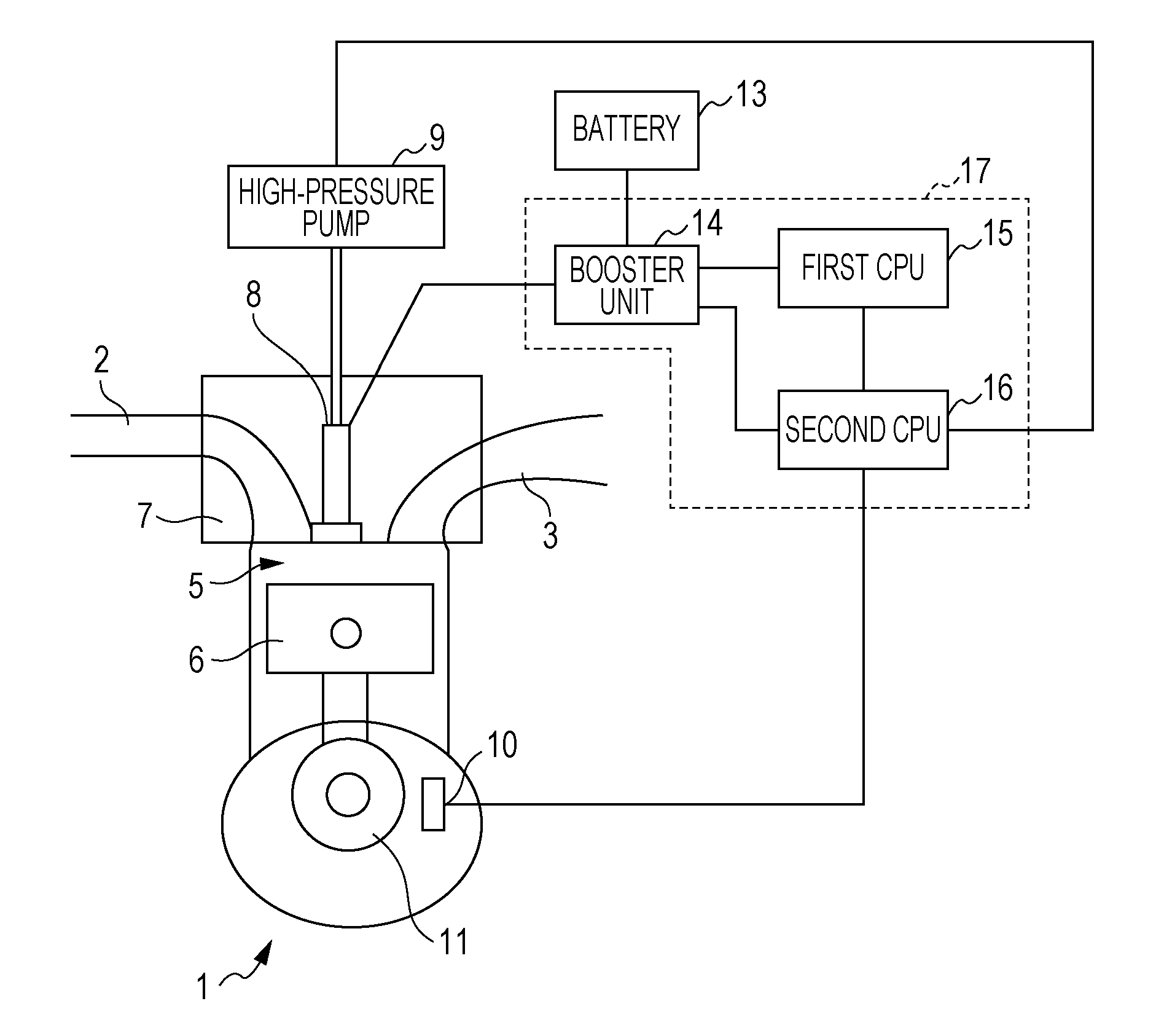
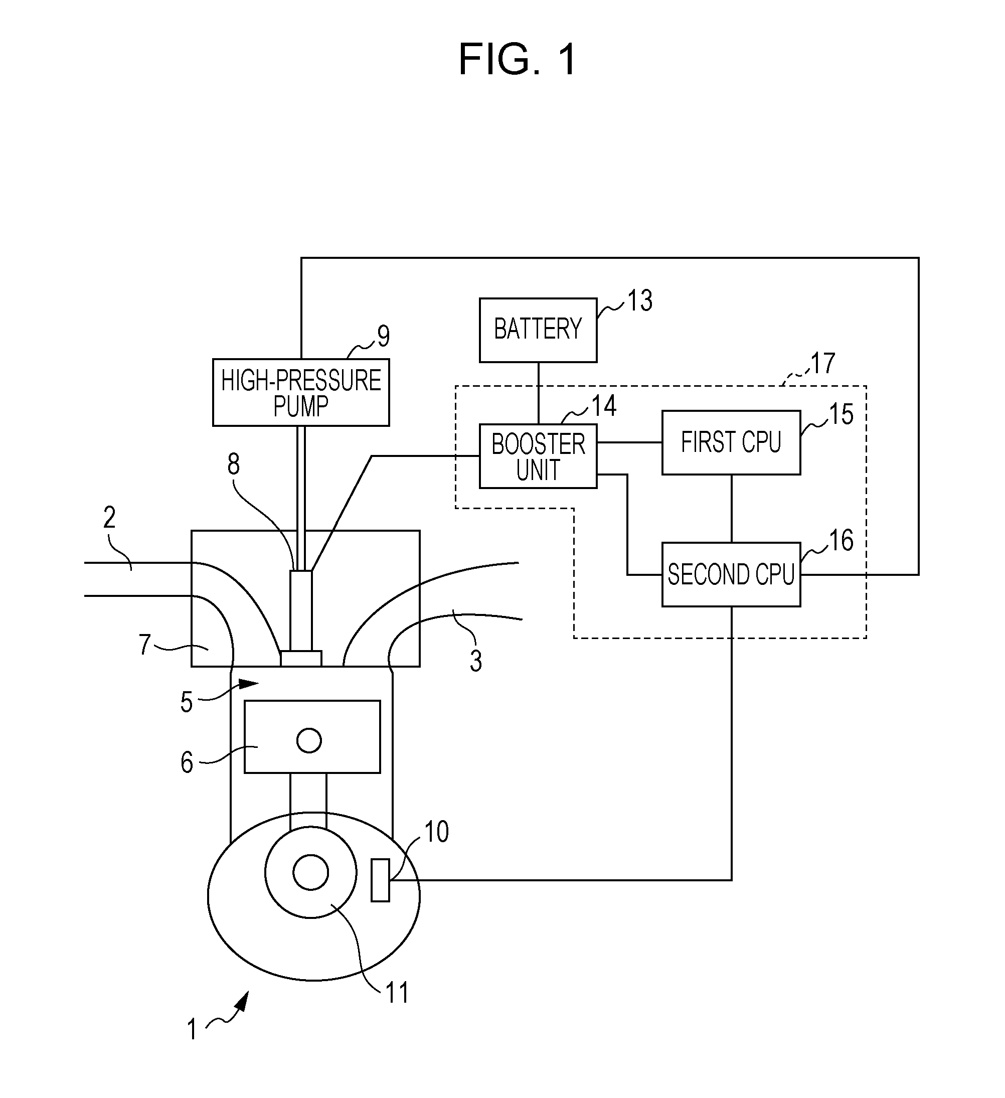
[0014]FIG. 1 illustrates an example of the entire configuration of a control apparatus for an internal combustion engine (hereinafter referred to as an engine) according to an embodiment of the present invention.

[0015]Referring to FIG. 1, an engine 1 is, for example, a four-cylinder four-cycle engine and only one cylinder is illustrated in FIG. 1. An intake pipe 2 and an exhaust pipe 3 are joined to the engine 1. A combustion chamber 5 is provided between a piston 6 and a cylinder 7. A fuel injection valve 8 is mounted so as to face on the combustion chamber 5.

[0016]The fuel injection valve 8 is connected to a high-pressure pump 9 and a fuel tank (not shown). The high-pressure pump 9 increases the pressure of fuel in the fuel tank to supply the fuel to the fuel injection valve 8. The fue...


PUM


Abstract

A control apparatus for an internal combustion engine includes a booster, a first controller, and a second controller. The booster is configured to increase an output voltage of a battery to a drive voltage of a fuel injection unit of the internal combustion engine. The first controller has a first initialization time after boot of the first controller. The first controller is configured to control the booster to increase the output voltage to the drive voltage at start-up of the internal combustion engine. The second controller has a second initialization time after boot of the second controller. The second initialization time is longer than the first initialization time of the first controller. The second controller is configured to control the booster to increase the output voltage to the drive voltage after the start-up of the internal combustion engine is completed.

Description

CROSS-REFERENCE TO RELATED APPLICATIONS[0001]The present application claims priority under 35 U.S.C. §119 to Japanese Patent Application No. 2010-260605, filed Nov. 22, 2010, entitled “Control apparatus for internal combustion engine”. The contents of this application are incorporated herein by reference in their entirety.BACKGROUND OF THE INVENTION[0002]1. Field of the Invention[0003]The present invention relates to a control apparatus for an internal combustion engine.[0004]2. Discussion of the Background[0005]Since fuel injection apparatuses that directly inject fuel into cylinders in internal combustion engines have relatively high drive voltages, the fuel injection apparatuses have heretofore increased their battery voltages to achieve the drive voltages. In this case, if it takes time to perform initialization after boot in electronic control units (hereinafter referred to as “ECUs”) controlling the drive voltages of the fuel injection apparatuses, there is a problem in that i...

Claims


Application Information

Patent Timeline
IPC IPC(8): F02D41/20
CPCF02D41/062F02D41/20F02D2200/101F02D2041/201F02D41/266
Inventor KITAMURA, NATSUKOIKEDA, AKITSUGU
Owner HONDA MOTOR CO LTD
Why Eureka
Try Eureka