High efficiency audio amplifier

Inactive Publication Date: 2012-05-31
GEHRKE ROBERT
View PDF2 Cites 8 Cited by
  • Summary
  • Abstract
  • Description
  • Claims
  • Application Information

AI Technical Summary

Benefits of technology

[0006]A battery-powered audio amplifier circuit is provided which comprises an operational amplifier. The operational amplifier is configured to receive an audio input signal, for example from an MP3 player, a radio, a cellular telephone, or any other source of electrical audio signals. The operational amplifier provides an audio output signal to a headphone, a loudspeaker, or any other audio device for converting electric energy into sound. The operational amplifier is operatively connected to a step-up converter, which provides a variable supply voltage Vcc to the operational amplifier. The step-up converter is powered by a battery having a voltage Vbat. The step-up converter is controlled by a microcontroller and configured to raise the operational amplifier variable supply voltage Vcc above the battery voltage Vbat. The audio amplifier circuit operates in one of multiple operating modes. Each of the multiple operating modes is characterized in that a distinct supply voltage Vcc is provided to the operational amplifier.
[0007]In one particular operating mode the step-up converter may be disabled, and battery voltage Vbatt may be applied directly to the operational amplifier. This particular operating mode with disabled step-up converter is preferably selected, if the output signal amplitude is low. If the output signal amplitude is high, the variable supp

Problems solved by technology

The amplifier's output voltage is inherently limited to stay below the supply voltage of the amplifier's end stage.
Audio clipping, a distortion of the audio signal, occurs, if the amplifier's end stage becomes saturated.

Method used


Image

  • High efficiency audio amplifier
  • High efficiency audio amplifier
  • High efficiency audio amplifier

Examples


Embodiment Construction

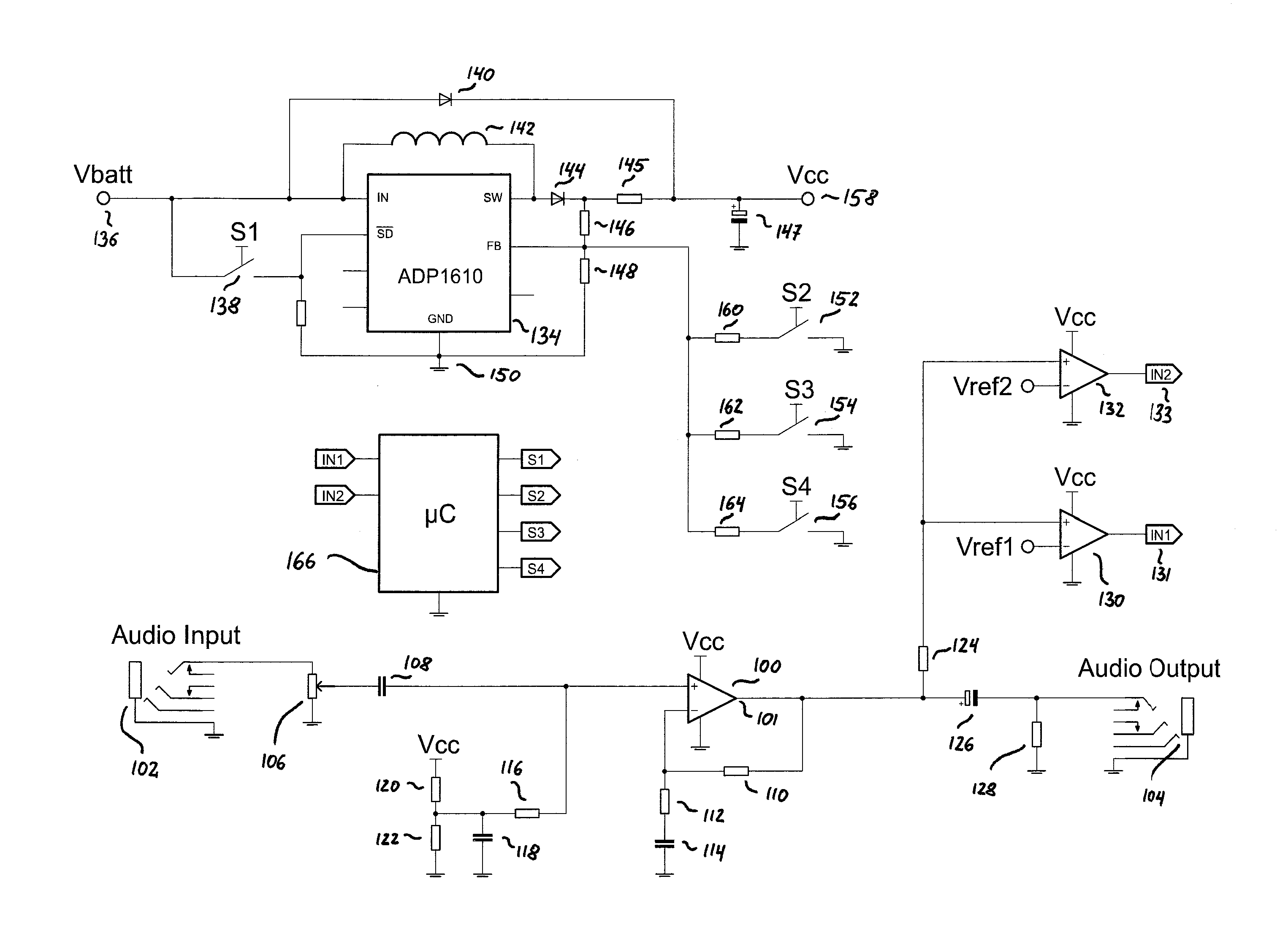
[0013]Referring to FIG. 1, a circuit diagram of an exemplary class G audio amplifier circuit 1 in which the principles of the present invention may be advantageously practiced is illustrated generally. The exemplary audio amplifier circuit 1 comprises an operational amplifier 100, which is configured to amplify an audio signal received from input connector 102, and provide an amplifier audio output signal to output connector 104. Connectors 102 and 104 may be standard 2.5 mm, 3.5 mm, or 6.4 mm stereo jacks. Input connector 102 may be used to connect an audio source, e.g. a portable MP3 player, a cellular telephone, a radio or the like. Output connector 104 may be used to connect a headphone, a speaker or the like.

[0014]The amplitude of the audio output signal at output connector 104 and thereby the volume of an attached speaker or headphone can be adjusted through potentiometer 106. Potentiometer 106 acts as a voltage divider for the audio input signal provided to input connector 10...


PUM


Abstract

An audio amplifier circuit is described which comprises an operational amplifier. The operational amplifier receives an audio input signal and provides an output suitable for connecting a headphone, or a loudspeaker. A step-up converter is provided which supplies the operational amplifier. The audio amplifier is configured to operate in one of multiple operating modes, each of which uses a distinct supply voltage Vcc of the operational amplifier in the audio amplifier. Comparators are used to compare the output voltage of the operational amplifier with a first reference voltage to raise the supply voltage of the operational amplifier, if clipping is imminent. A second comparator is used to compare the output voltage of the operational amplifier with a second reference voltage, indicating that the supply voltage of the operational amplifier can be lowered without the risk of clipping.

Description

TECHNICAL FIELD[0001]The present invention generally relates to amplifier circuits, and more particularly, to high efficiency amplifier circuits for use in battery powered applications.BACKGROUND OF THE INVENTION[0002]Portable audio devices, such as for example MP3 players, radios, or external headphone amplifiers, are typically powered by a battery. The battery's voltage limits the maximum amplitude of the amplifier's output, and thereby the volume of an attached speaker or headphone. The amplifier's output voltage is inherently limited to stay below the supply voltage of the amplifier's end stage. Audio clipping, a distortion of the audio signal, occurs, if the amplifier's end stage becomes saturated.[0003]Class G audio amplifier circuits are known to conserve power and avoid audio clipping by adjusting the voltage that is supplied to an amplifier's end stage. An exemplary class G headphone amplifier circuit is disclosed in U.S. patent application Ser. No. 12 / 255,537, which is her...

Claims


Application Information

Patent Timeline
IPC IPC(8): H03G3/20
CPCH03G1/0088H03G3/3005H03F1/0244H03F2203/45138H03F3/45475H03F2200/511H03F3/187
Inventor GEHRKE, ROBERT
Owner GEHRKE ROBERT
Why Eureka
Try Eureka