Fuel cell

Active Publication Date: 2014-05-22
TOYOTA JIDOSHA KK
View PDF9 Cites 4 Cited by
  • Summary
  • Abstract
  • Description
  • Claims
  • Application Information

AI Technical Summary

Benefits of technology

The present invention can improve the wet state and increase the output voltage.

Problems solved by technology

This may increase the passage resistance in the cathode-side flow passage, and thus may cause reduction of electric power generation output.

Method used


Image

  • Fuel cell
  • Fuel cell
  • Fuel cell

Examples


Embodiment Construction

[0021]An embodiment of the present invention will be described below based on the drawings. However, the embodiment below is an example, and the present invention is not limited to this embodiment.

[0022]A basic structure and a basic principle of the present embodiment will first be described.

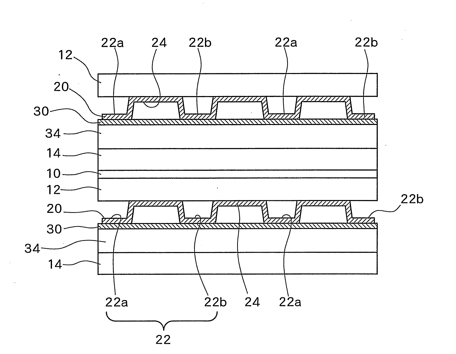
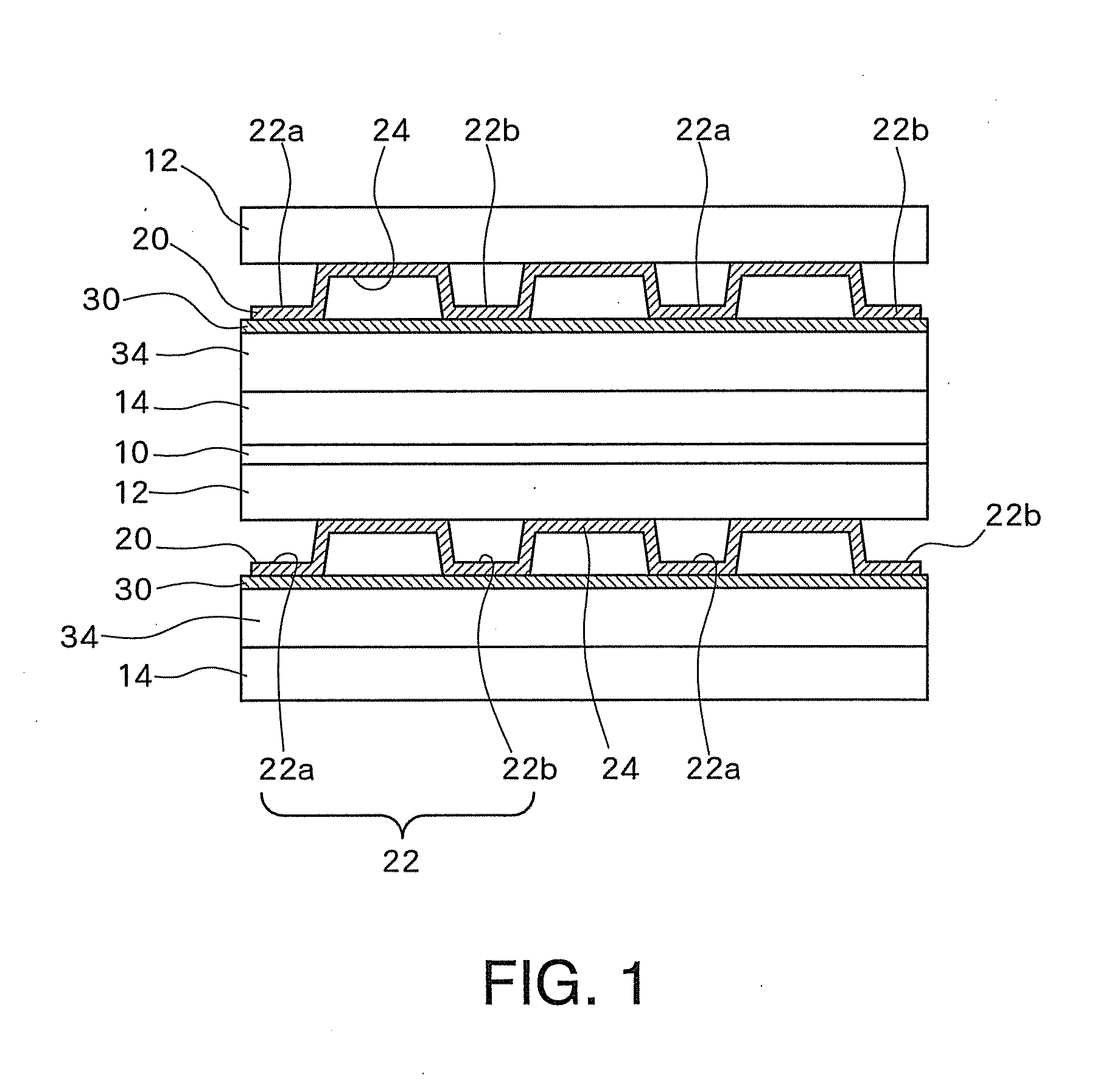
[0023]A fuel cell according to the present embodiment has an MEA, an anode-side gas diffusion layer, and a cathode-side gas diffusion layer, and a separator having a convex and a concave formed as the front and back sides thereof is joined to the anode-side gas diffusion layer. Because the separator is formed by pressing, it is referred to as a “press separator”, when necessary. A concave portion of the anode-side gas diffusion layer of the press separator functions as a gas flow passage and is supplied with hydrogen gas as a reactant gas. In addition, a convex portion adjacent to the concave portion, which is a concave portion on the back surface, functions as a coolant flow passage and is supp...


PUM


Abstract

Provided is a fuel cell, the output voltage of which is improved by making a membrane moist state uniform. An anode-side gas diffusion layer and a cathode-side gas diffusion layer are joined to a membrane electrode assembly, and a separator is joined to the anode-side gas diffusion layer. The separator has a recess portion and a protrusion portion formed to constitute a gas flow path and a refrigerant flow path, respectively. The cross-sectional area of the recess portion is made relatively small at the downstream side in comparison with that at the upstream side, and the cross-sectional area of the protrusion portion is made relatively large at the downstream side in comparison with that at the upstream side, thereby improving the moist state.

Description

TECHNICAL FIELD[0001]The present invention relates to a fuel cell, and particular to a structure of a separator.BACKGROUND ART[0002]In a polymer electrolyte fuel cell, a cell is formed as a minimum unit by sandwiching a membrane electrode assembly (MEA), which is composed of a fuel electrode and an air electrode sandwiching an electrolyte membrane formed of a polymer electrolyte membrane, with two separators, and a plurality of cells are stacked to form a fuel cell stack, which can provide high output.[0003]The mechanism for electric power generation employed by the polymer electrolyte fuel cell is well known, and in a nutshell, fuel gas, such as hydrogen-containing gas, is supplied to the fuel electrode (i.e., anode-side electrode), and oxidant gas, such as a gas mainly containing oxygen and air, is supplied to the air electrode (i.e., a cathode-side electrode). The hydrogen-containing gas is supplied to the anode-side electrode through a fuel gas flow passage, and is dissociated i...

Claims


Application Information

Patent Timeline
IPC IPC(8): H01M8/04
CPCH01M8/04029H01M8/0254H01M8/0265H01M8/0267H01M8/1004H01M8/0263H01M8/10H01M8/02Y02E60/50
Inventor HAMADA, SHIGETAKA
Owner TOYOTA JIDOSHA KK
Why Eureka
Try Eureka