Image magnifier for the visually impaired

a magnifier and visual impairment technology, applied in the field of viewing devices, can solve the problems of limiting the ability of individuals with low vision to lead an independent life, difficulty in reading small writing or discerning small objects without high magnification, etc., and achieves the effects of reducing the size of the magnifier, facilitating transportation, and not being able to fold

Inactive Publication Date: 2009-03-05
TECH HUMANWARE
View PDF18 Cites 59 Cited by
  • Summary
  • Abstract
  • Description
  • Claims
  • Application Information

AI Technical Summary

Benefits of technology

[0014]The Videomatic Uno from Reinecker Reha-Technik GmbH is another prior art low-vision magnifier. In this device the camera and lights are mounted on a rigid stand above the base, comprising a head unit, two uprights at the back and a flat base unit with an X-Y table. A flat-panel display is mounted to the front of the head unit by two pivots at either side of the bottom of the display. The display may be swung upright for normal use or swung back and down so that the display covers the top of the head unit and faces up. This reduces slightly the size of the magnifier for transportation, but because the stand stays rigid and cannot be folded the magnifier is too large to be easily transported. Further the front of

Problems solved by technology

Low vision can be caused by a variety of eye problems.
Individuals with low vision find it difficult, if not impossible, to read small writing or to discern small objects without high levels of magnification.
This limits their ability to lead an independent life.
The need for space around the X-Y table makes it difficult to place VDU's or other objects in the immediate vicinity.
Moving the X-Y table 5 in this way can be tiring for the user's arms and their eyes.
The design of the prior art video magnifier also causes several limitations to the viewing area.
Typically the maximum viewing area of such a system is about 1/10 of the area of an A4-sized page, so it is not possible to view a whole A4 page at once.
Therefore the device is typically large, heavy and not easily transportable.
This requires a high level of dexterity from the user.
This reduces slightly the size of the magnifier for transpo

Method used


Image

  • Image magnifier for the visually impaired
  • Image magnifier for the visually impaired
  • Image magnifier for the visually impaired

Examples


Embodiment Construction

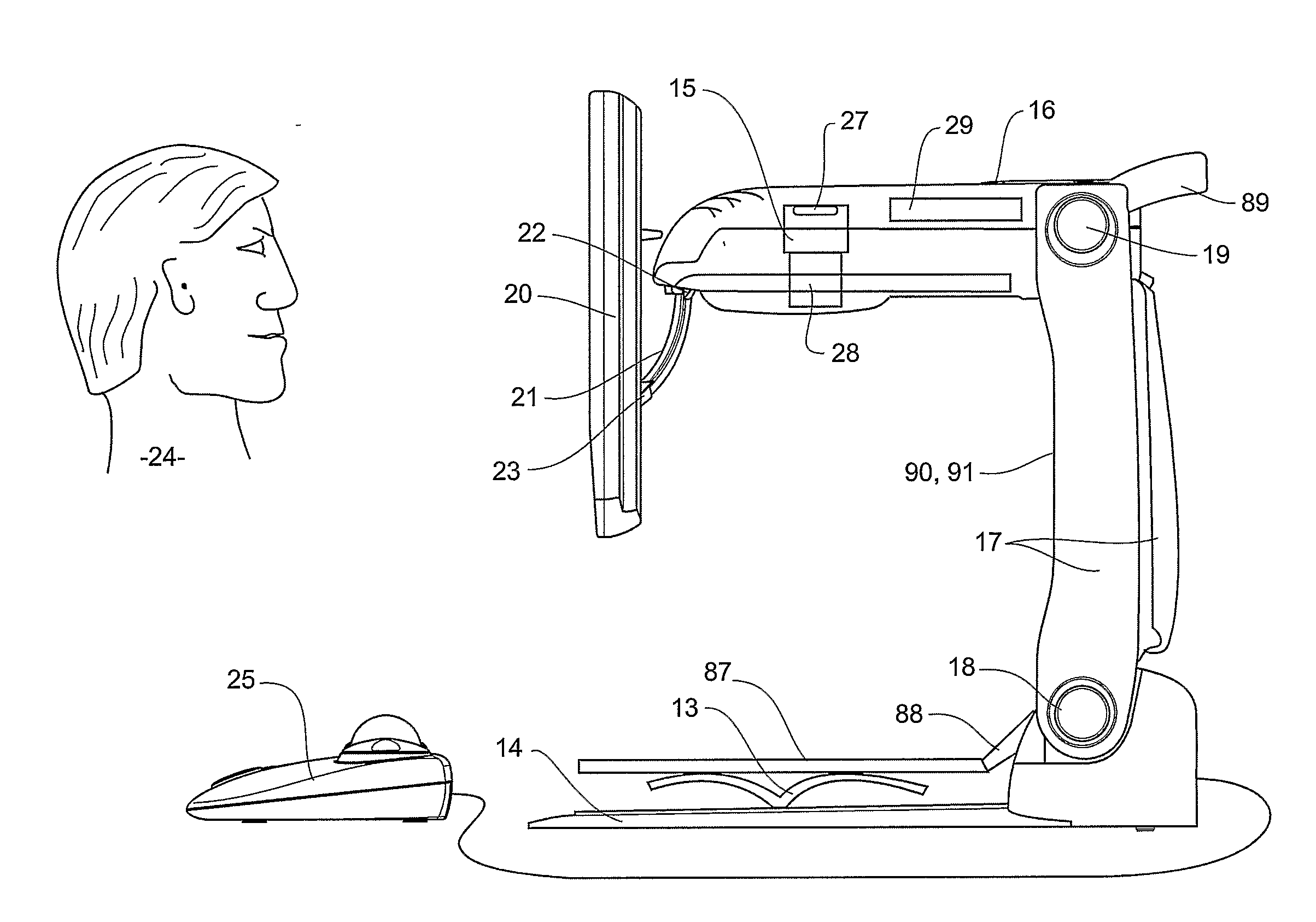
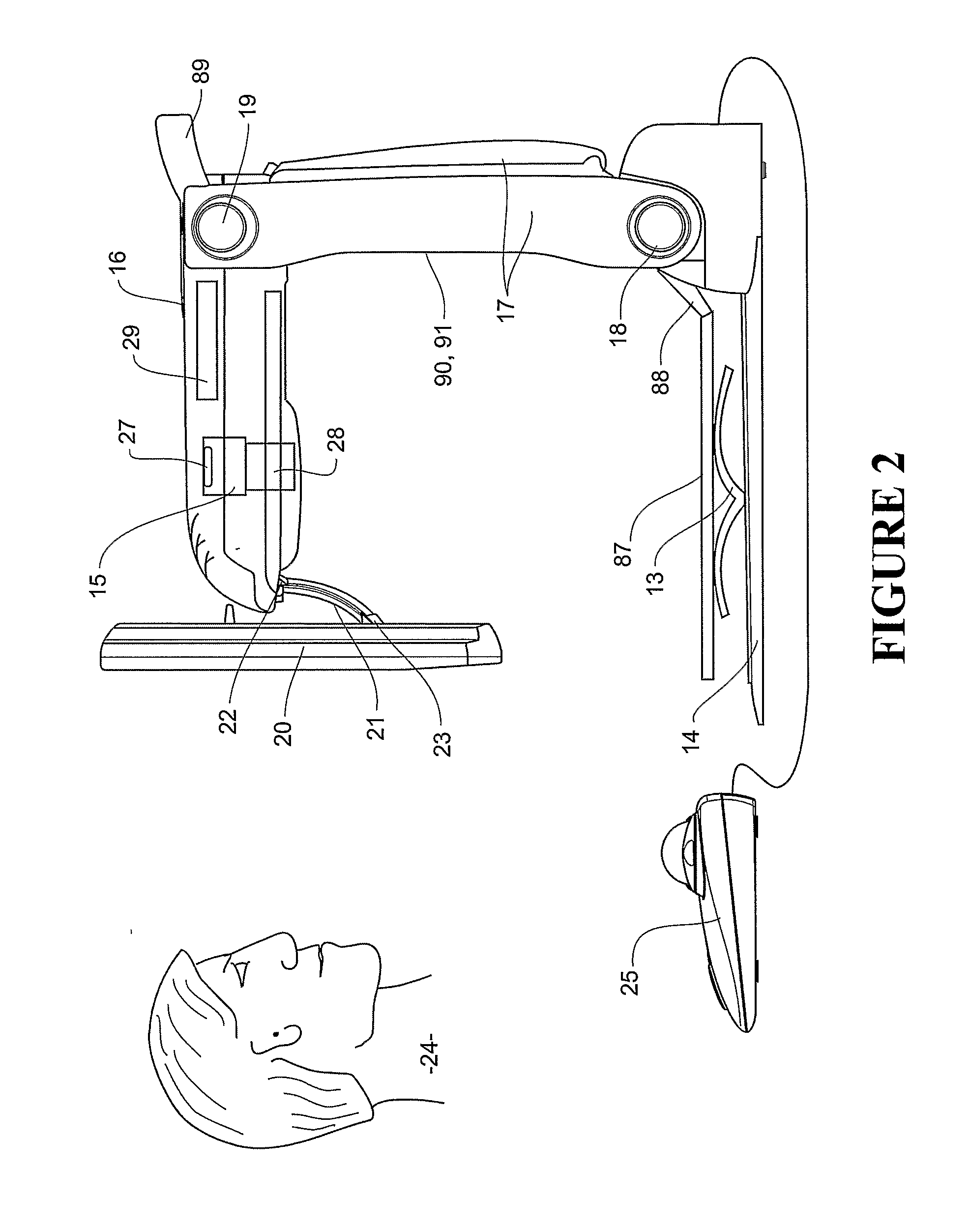
[0102]The image magnifier for the vision impaired of the present invention magnifies the image of face-up source material placed in the visual field of the camera and displays the magnified image on a VDU or other display means. Preferably there are two different camera modes. The first mode is a static mode whereby the camera captures and stores a single high-resolution image of the source material. This high-resolution image can be manipulated and displayed on the display means. The second mode is a live mode whereby the camera captures consecutive lower resolution images at a high frame rate so as to provide full motion video. Using the live mode the low-vision user can move the view around the source material and magnify a desired section of interest. Preferably the same camera and the same apparatus are used for both the static and live modes.

[0103]In static mode the software controlling the system captures and manipulates a high-resolution image. This allows precise pixel data...


PUM


Abstract

A image magnifier for the vision impaired which magnifies the image of face up source material (13) placed in the visual field of the camera (15) and displays the magnified image on a display (20). One embodiment includes a static high-resolution image mode and a second live video mode. The controller (29) provides different lighting appropriate for each mode. In a further embodiment the magnifier is transportable. Each part (17, 14, 16) is hinged (18, 19) to the other parts (17, 14, 16) allowing it to be folded into a compact lightweight form to be portably carried. In a still further embodiment the magnifier includes shielding for the lighting to minimise or avoid specular reflections.

Description

BACKGROUND OF THE INVENTION[0001]1. Field of the Invention[0002]This invention relates to a viewing device to enable people with low-vision to view objects or source material, including reading text, handwritten or printed, viewing pictures and physical objects, and particularly, but not solely, relates to a foldable device including a camera, a visual display unit (VDU), a variety of light sources and a control unit to activate a variety of viewing modes.[0003]2. Summary of the Prior Art[0004]Low vision is defined as a condition where ordinary eye glasses, lens implants or contact lenses cannot provide sharp sight. Low vision can be caused by a variety of eye problems. Macular degeneration, diabetic retinopathy, inoperable cataracts, and glaucoma are but a few of the conditions that cause low vision. Individuals with low vision find it difficult, if not impossible, to read small writing or to discern small objects without high levels of magnification. This limits their ability to l...

Claims


Application Information

Patent Timeline
IPC IPC(8): H04N5/262H04N5/64G09B21/00H04N1/00H04N1/195H04N1/387H04N5/225
CPCG09B21/001H04N1/00347H04N1/195H04N1/19594H04N5/2256H04N2201/045H04N2201/0089H04N2201/0096H04N2201/043H04N2201/0436H04N2201/0081H04N23/56
Inventor SEAKINS, PAUL J.CARTWRIGHT, JONATHAN D.HAUGHEY, DAVID J.LOVEGROVE, DAVID N.BEST, DARRYL J.
Owner TECH HUMANWARE
Why Eureka
Try Eureka